Overkill or insufficient. When it comes to selecting the standalone solution for your racecar, it’s really easy to spend too much on an Engine Management System (EMS) that does more than you actually need. For those that have tons of disposable income, that’s probably not a major concern. Just buy the best standalone ECU and sensor package, get a custom motorsports harness, hire the best calibrator for your particular ECU, and $15K-$40K later – call it a day. For the rest of us that skip meals to buy performance parts, wasting money on an overkill EMS solution (if it can even be obtained by maxing out all of the credit cards) limits the amount of money available for other upgrades. It’s stupid. However, not spending enough and ending up with an EMS that doesn’t do enough will be even more costly in the long run if the system must be upgraded. That’s even more stupid. Since you can’t fix stupid, getting educated is the only way to get the right EMS solution that does everything you need without spending too much. For the first part in this tech series, we will start by covering EMS operational basics before taking a close-up look at the input side of the system. Future parts will explore the output side of the system along with configuration and setup considerations.
Text by Michael Ferrara // Photos by Joe Singleton
DSPORT Issue #188
Disclaimer
If you are interested in distributors, wasted-spark ignition and batch-fire or semi-sequential fuel injection schemes, stop reading! The following information is for those interested in modern engine management that implements the necessary engine controls to optimize performance, efficiency, and reliability. Anyone taking the time, money, and effort to run a standalone system should run a sequential fuel injection system with a dedicated coil per-plug ignition system. This is the only way to have independent fuel and ignition control for each individual cylinder.
EMS Basics
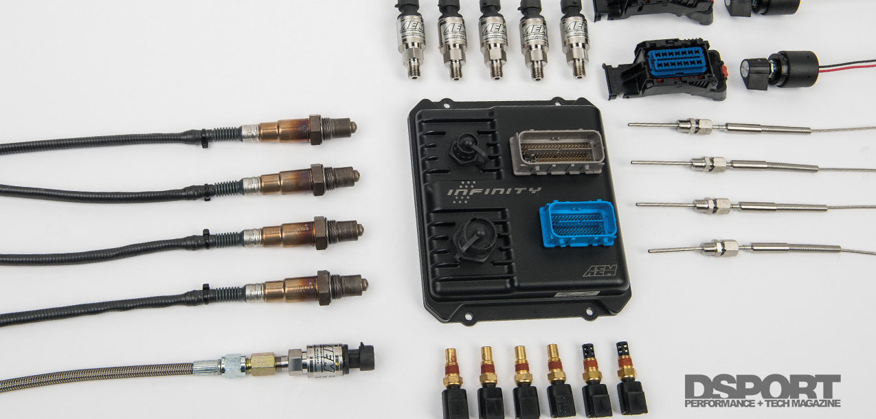
For the sake of our discussion, we will refer to the EMS as the system that includes the ECU dedicated to engine management along with the sensors. In the simplest terms, the EMS takes a number of inputs, performs a series of calculations, and produces a number of outputs. Inputs are fed to the ECU via sensors and in some applications on a CAN bus where other vehicle computers (transmission, ABS, vehicle dynamics, etc.) report information (vehicle wheel speeds, transmission parameters, and accelerometer data). The ECU takes this data and processes it, performing calculations, looking up table information, and ultimately controlling an output. Different ECUs may employ different strategies and algorithms to determine the output. One ECU might use as little as five inputs, while another may use as many as 20 inputs to establish exactly when and for how long to open a fuel injector. Higher-end ECUs will generally allow for a higher number of inputs while boasting additional processing power. When properly configured, the end result can be more accurate outputs that deliver an optimized amount of fuel or spark timing. Even before any calibration takes place with the standalone ECU, the setup and configuration of the system will determine if success will be possible.
The Essential Sensors
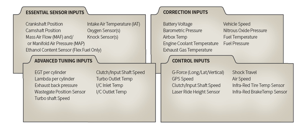
In journalism, police investigation, and problem solving; there are the five Ws: Who? What? Why? Where? And When? These questions constitute the formula for getting a complete picture or story of a situation. In a similar fashion, the ECU also needs to have a number of essential questions answered in order to get the complete picture and to perform accordingly. We’ve grouped these sensors as the essential sensors for the ECU.
Crankshaft and Cam Position Sensors
The crankshaft and camshaft position sensors that tell the ECU the engine speed (RPM) and exactly where each piston is in the four-stroke process. Thanks to this information, the ECU can fire ignition coils and injectors at the right time. A number of other outputs controlled by the ECU also take engine speed into consideration. For example, the boost-control solenoid is always dependent on engine speed. Often overlooked, the quality of the input signals from the camshaft and crankshaft sensors can significantly affect the throttle response of the engine. The type of sensor and its location impact the quality of the information sent to the ECU (Look for a dedicated tech article on the subject in the next issue).
Engine Load Sensors
Equally important to the sensors that establish the engine speed and piston position are the sensors used to establish the “load” on the engine. Load is most often referenced in terms of the mass air flow though the engine in the units of grams per second. There are four potential sensors that can be used to measure, estimate, or compute load. These include Throttle Position Sensor (TPS), Mass Air Flow (MAF) sensor, Manifold Air Pressure (MAP) sensor, and Intake Air Temperature (IAT) sensor.
By using one or a combination of all four of these sensors, there are four distinct strategies that can be employed to determine engine load. Most aftermarket ECUs allow for a blending of these strategies. By itself, each one of these strategies has its advantages and shortcomings (see “get a load of this” sidebar). Currently, combining an Alpha-n strategy (TPS sensor) with speed density (MAP plus IAT) compensation is proving to provide the best results for most performance applications.
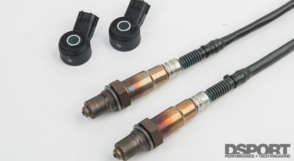
Feedback from the universal exhaust gas oxygen and knock sensors allows the ECU to adjust the air/fuel mixture or timing for optimum engine performance.
UEGO and Knock Sensors
While the position sensors and load sensors can run an engine by themselves, there are two “feedback” sensors that have worked their way onto the essential sensor list. These are the exhaust gas oxygen (O2 sensors) and knock sensors. The wideband exhaust gas oxygen sensor(s) tell the ECU the actual running air-fuel ratio of the engine. The ECU can compare these values to the desired or targeted values and make corrections as needed. Today, ECUs rely upon this feedback and correction strategy even under WOT conditions. Ideally, the mapping of the engine is done properly so that corrections are kept to a minimum. However, air filters and fuel injectors can become dirty and flows can be off the ideal, so corrections need to be made even if the engine was properly calibrated. The knock sensor(s) also provide valuable feedback to the ECU. These microphones listen to the engine to identify knock. When this undesirable knock is detected, the ECU can reduce ignition timing advance to eliminate the knock. Whereas the O2 sensor provides the feedback for the fueling to be corrected under certain conditions, the knock sensor(s) do the same with respect to the ignition timing calibration. A tank of bad fuel might induce knock on an otherwise properly tuned and calibrated engine. The knock sensor and an active knock response strategy in the ECU can keep the knock to a minimum.
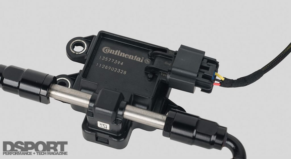
A flex fuel sensor will be able to report the ethanol content of the fuel to the ECU. Supplied with this information, the tuner calibrated maps in the ECU can adjust fuel, ignition and boost trims and targets accordingly.
FLEX Ethanol Content Sensors
On applications where flex fuel is being used (various gasoline ethanol blends), an ethanol content sensor is essential. The ethanol content sensor reports the percentage of ethanol present in the fuel which allows the ECU to set fuel, ignition, and boost targets accordingly.
Correction Sensors
Only second in importance to the essential sensors, the correction sensors provide information to the ECU that allow for necessary compensations to be made based on conditions.
Battery Voltage
Integrated within every ECU is a battery voltage sensor. By knowing the battery voltage, the ECU can adjust the charging time for the ignition coils. The ECU reduces the amount of time for charging as voltage increases, and increases the charging time as voltage decreases. This ensures that the coils have a sufficient amount of energy to fire the spark plugs without getting too much of a charge to cause the coil to overheat and fail. A change in battery voltage also affects the delivery of fuel from the fuel injectors. As voltage increases, the injector will deliver more fuel for a given pulse-width signal. If the ECU has the correct injector data and the battery voltage information, it can avoid a rich or lean condition as battery voltage changes. While they shouldn’t be individually fused, the ECU, injectors and coils should all see the same voltage (+/- 0.2v).
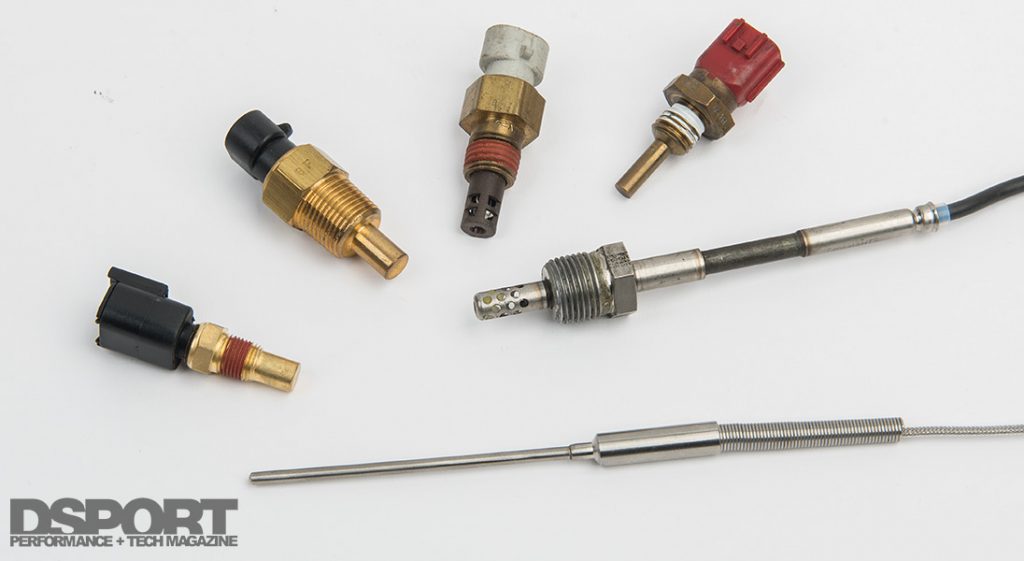
Coolant Temperature Sensor (CTS)
A cold engine requires more fuel and ignition timing advance than a warm engine to avoid misfires. The engine coolant temperature sensor reports the temperature of the coolant in the engine to the ECU. The ECU uses this data to enrich fuel delivery on the cold engine and advance the ignition timing. The coolant temperature sensor input can also be used to allow the ECU to trigger cooling pumps and electric cooling fans as needed. The CTS data can also be used to set a cold-engine rev limiter or to limit boost, power, or engine speed when coolant temperatures are excessive.
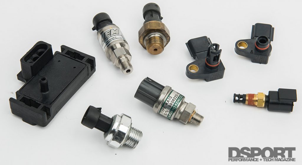
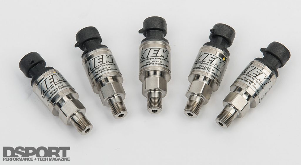
Various pressure sensors will be used with a typical engine management system. MAP sensors are one type of pressure sensor. MAP sensors are absolute range meaning that they start at full vacuum and go up to zero vacuum or “boost” pressure limit. Pressure sensors that are based on gauge pressure are typically used everywhere else. These sensors have a range that starts at 0psi and ends at 75, 100, 150, 250, 500, 1000, 1,500psi or more.
Barometric Pressure (BARO)
While not needed on MAF based systems that directly measure the airflow into the engine, all other engine-load-determination strategies are affected by changes in atmospheric pressure (a.k.a. barometric pressure). By including a barometric pressure sensor in the EMS, fuel delivery can be trimmed as atmospheric conditions get lower in pressure (weather or altitude changes).
Fuel Pressure (FP)
While the airflow into the engine can either be directly measured by an MAF sensor or calculated by a Speed Density strategy (manifold pressure and temperature), it’s just as important for the ECU to know how much fuel is being delivered to the cylinders. In order for this to happen, the performance characteristics of the injectors must be known by the ECU. The ECU needs to know how the injector responds to different fuel pressures and different supply voltages. This information is usually provided by the injector’s manufacturer. However, the ECU needs to have an accurate measurement of the fuel pressure in order to calculate the amount of fuel delivered. Hence, a fuel pressure sensor is one of the most important correction sensors in the mix. In addition, the fuel pressure sensor is also useful in determining if the fuel supply system is inadequate (indicated by an inability for the fuel pressure to remain constant under high loads).
Exhaust Gas Temperature (EGT)
Before the advent of affordable, high-performance UEGO sensors to determine air-fuel ratio, Type K thermocouples serving as EGT sensors were the go to monitor for tuning. On a gasoline engine, EGTs will rise as the air-fuel ratio gets lean. Unfortunately, EGTs will also rise when there isn’t enough ignition timing advance and the combustion is started late so that the energy ends up in the exhaust instead of in the cylinder. Hence, EGT information by itself isn’t enough. However, when the air-fuel ratio is known thanks to the UEGO sensor, EGT sensors can provide extremely valuable information for the tuner to help set a proper ignition timing curve. Many tuners still mistakenly believe that the Forrest Gump approach of “rich (fuel) and retarded (timing)” is the safe route. In actuality, running an excessively rich mixture with retarded ignition timing is the quickest way to burn up exhaust valves or to overheat exhaust manifolds to the point of warpage and cracking.
Vehicle Speed Sensor (VSS)
If the ECU knows the speed of the vehicle, it will be able to determine the current gear being used (since it already knows the engine speed). Knowing both the vehicle speed and the gear allows many types of corrections to be made. It is possible to run a different boost target in each gear. It is possible to perform a fuel trim or enrichment in specific gears as needed. It is possible to shut off the coolant fans at a set vehicle speed. Many speed and gear based corrections can be made if the vehicle speed is known.
Nitrous Oxide Pressure (NOP)
The amount of nitrous oxide delivered when the system is activated is predicated upon the size of the jetting used and the pressure that the system is operating at. By incorporating a nitrous-oxide pressure sensor in the system, the ECU can make fuel delivery corrections to compensate for drops in bottle pressure while the system is in use. Of course, there is no need for this sensor when a nitrous oxide system is not installed.
Strain Gauge Shifter (SGS)
In applications where a clutchless shift is desired, a strain-gauge attached to the shifter can alert the ECU that a gear change is going to be made. When the ECU gets the notice that the shifter is being pushed or pulled for a gear change, it is able to momentarily kill engine power to allow for a clutchless shift.
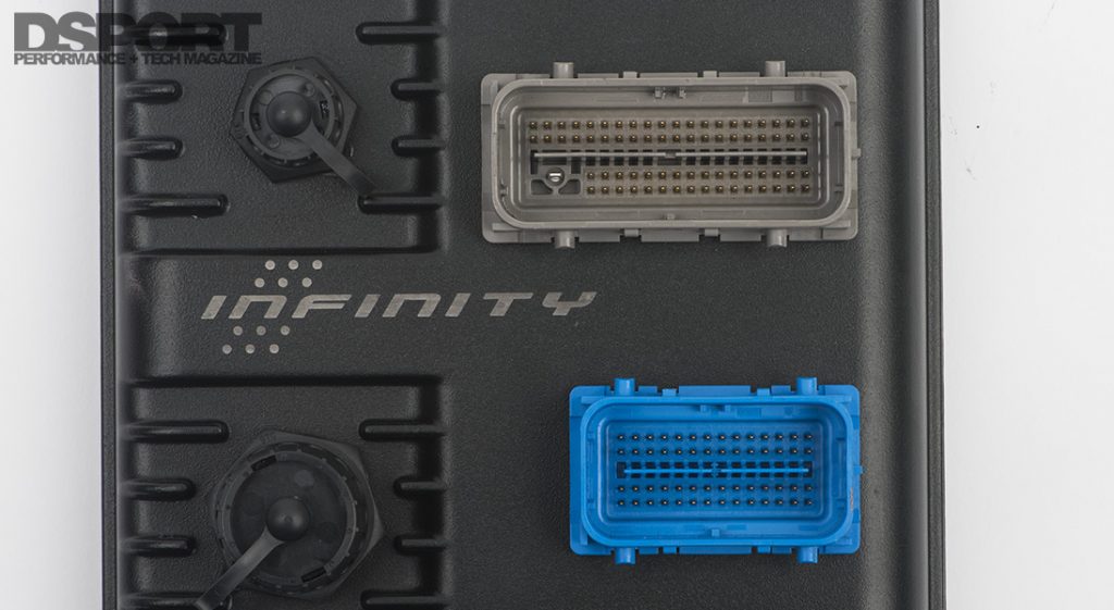
The number of pins on an ECU used to be a basic indicator of how many inputs and outputs an ECU could handle. Today, many inputs are fed to some ECUs through a CAN channel. So pin count isn’t the only indicator of the total number of input channels.
GET A LOAD OF THIS
Alpha-n
One of the simplest load-determining strategies is termed Alpha-n. This strategy solely relies upon throttle position to establish engine load. If the Throttle Position Sensor (TPS) is reporting 1.0 percent with the throttle closed at idle, the load is at its minimum. If the throttle is wide open and reporting 100 percent, the load is at its maximum. Any throttle positions between the two extremes establish the load. Hence, if the TPS is reporting 50-percent, the load is 50-percent. During the tuning process, a fuel delivery table is built that establishes the injection time at a range of engine speeds and throttle positions. By itself, this strategy can only be employed on naturally-aspirated applications. It is most popular on race-only individual throttle body applications with big cams where employing an MAF sensor or MAP sensor may be a challenge. When combined with a Manifold Air Pressure strategy to compensate for boost and actual changes in load, the Alpha-n + MAP Compensation solution can prove to be extremely effective.
Advantages: Direct-measurement strategy that requires least processing by ECU. Crisp throttle response at the actual load that the mapping is conducted on.
Disadvantages: Does not compensate for actual changes in the load on the engine of changes in barometric conditions. Delivers same fuel per RPM at a given throttle percentage whether the engine is lightly loaded in a cruise or coast condition (high engine vacuum) or in a high load situation going up a hill (low vacuum condition). Has no compensation for changes in air density, so altitude changes wreak havoc on the tune. Alpha-n is not a recommended strategy, by itself, for any application.
Speed Density (D-Jetro)
By using the input from the Manifold Air Pressure (MAP) and Intake Air Temp (IAT), a speed-density strategy accurately estimates the mass air flow through the engine under most conditions. In speed density applications, the main fuel table will have engine speed versus MAP voltage on the axes. A secondary enrichment table will apply a set amount of enrichment based on the intake air temperature. The cooler the temperature reported by the IAT, the more fuel that will be added as the charge air is denser at the cooler temperature.
Advantages: Does not restrict airflow like a Mass Air Flow (MAF) sensor. Accurately senses changes in load under most conditions.
Disadvantages: Intake air temp sensors respond slowly. As a result, computed airflows during fast and large temperature changes contain more error. Applications that have low MAP signals (big-cam engines) will have inconsistent A/F ratios at idle and low engine speeds.
Mass Air Flow (L-Jetro)
In a Mass Air Flow strategy, an MAF sensor directly reports to the ECU the actual mass air flow through the engine. Under the conditions where the MAF is accurately reporting the air flow, the ECU is able to accurately supply the correct amount of fuel easily. Up until the flow limit of the MAF sensor is reached, the MAF strategy is most likely to deliver accurate fueling requiring the smallest amount of short-term feedback correction. Due to this level of accuracy, most OEMs use MAF-based fuel delivery as the primary strategy to achieve reduced emissions and improved fuel economy. Unfortunately, these systems are highly sensitive to the actual placement of the sensor. Any leaks between the MAF sensor and the throttle body will allow unmetered air to enter the engine, causing undesirable air/fuel ratios that require serious correction.
Advantages: Direct-measurement strategy that requires least processing by ECU. Can provide extremely accurate mass air flow info to ECU even with low-MAP signal applications.
Disadvantages: System is very dependent upon the quality and calibration of the MAF sensor. Location and placement of the sensor have a large impact on the performance. Many MAF sensors cannot support higher flow (horsepower) applications, requiring multiple sensors. MAF sensors have delicate components that can become fouled, thus reporting improper flows.
Delta-P Modeled Flow
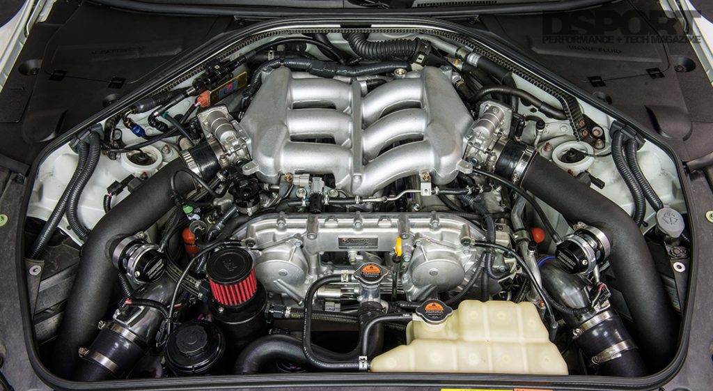
While not an option for universal applications, another strategy can be successfully employed that seems to offer the benefits of the other strategies without any of the drawbacks. When a MoTeC M1 system is installed on an R35 GT-R, the ECU uses the difference in pressure before and after the throttle body along with the throttle angle to calculate airflow. Under laboratory conditions, MoTeC was able to completely measure the actual flow rates across the throttle bodies of the VR38DETT engine. These measured values are put into a lookup table that allows the ECU to know the actual airflow based solely on throttle positions and the pressure difference across the throttle body.
Advantages: Provides MAF-system like accuracy for mass air flow without the drawbacks associated with an actual MAF sensor.
Disadvantages: Limited applications currently.
While TPS (Alpha-n), Mass Air Flow and Speed Density are the traditional trio of engine load measurement strategies for ECUs, the MoTeC M1 for the R35 GT-R uses the pressure and temperature difference across the throttle body to determine mass airflow.
Wheel Speed Sensors (WSS)
If traction control is on the agenda, the ECU is going to need to know the speed of each of the wheels on the vehicle (or at least one front and one rear). All modern ABS equipped vehicles will have individual speed sensors that can be tapped into to provide this information to the ECU. On some applications, the information may also be available by CAN.
GPS Speed Sensor (GPS)
For all-wheel-drive vehicles or vehicles that lift the front wheels upon a launch, traction control cannot be implemented in a conventional fashion because there will be conditions where none of the wheels are showing the actual vehicle speed. For these applications, a GPS speed sensor can be used to assist with the traction control strategy. Faster sensors allow for better traction control performance. Currently, a 20Hz sensor is the quickest available. It updates the speed to the ECU at a rate of once every 50ms. Slower 5Hz and 10Hz units only update every 200 and 100ms, respectively.
Advanced Tuning Sensors
There are a group of sensors that can provide valuable input to the ECU to allow for precise calibration of the EMS. Many of these sensors can also be used to evaluate the quality of the match of a turbocharger to a particular engine combination. While these sensors are valuable during dyno and on-track sessions to fine tune the calibration, many of them won’t provide valuable data after the calibration is completed. In situations where your ECU has limited input channels, many of these can be removed from the system after the calibration is completed.
EGT per cylinder
Due to the relatively low cost of the sensors, using one EGT sensor per cylinder is a great way of monitoring variance in cylinder-to-cylinder air-fuel ratios for individual fuel cylinder fuel trims. In general, these sensors are also quite robust.
UEGO per cylinder
High-performance UEGO sensors are less expensive than ever before. With some of the newer models providing a CAN output, these sensors no longer eat up all of the available analog inputs. Since backpressure affects and skews the reading from the UEGOs, an exhaust backpressure sensor must also be used. This is the best method for setting individual fuel trims per cylinder to ensure all cylinders have the same air-fuel ratio.
Exhaust Back Pressure
The data from this sensor is required when UEGO sensors are run before the turbine on turbocharged applications. In addition to providing the data necessary for correct air-fuel ratios under those conditions, an exhaust backpressure sensor can be used to help determine the ideal turbocharger match for a particular engine combination. Comparing the amount of exhaust backpressure to boost pressure can be a great indicator if the turbine section is too small.
A wastegate position sensor is a window into the operation of your turbo system. By data-logging the position of the valve this sensor provides insight into what is happening in relation to other engine operating activity.
Wastegate Position Sensor
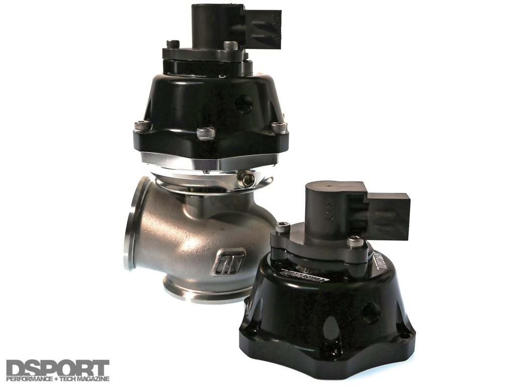
By incorporating a wastegate position sensor, the exact amount of wastegate opening can be logged. In looking at this data, a determination as to whether or not the wastegate is too small or too big can be determined. While it is rare for an import application to have too little wastegate capacity when an external wastegate is used, it is very common for there to be too much wastegate capacity.
Turbo Shaft Speed Sensor
If you’ve ever looked at a compressor map for a turbocharger, you will notice that the y-axis is the pressure ratio (a number obtained by simply dividing the compressor outlet pressure by the barometric pressure), while the x-axis is the flow rate. A number of swooping lines show different shaft speeds. By knowing the shaft speed and the pressure ratio, one can find not only the flow rate from the turbocharger, but also the efficiency at that point. This information is critical in determining if the turbo is properly matched to the engine combination. The shaft speed sensor can also warn the tuner of an overspeed situation that can cause the compressor wheel to explode.
I/C Inlet and I/C Outlet Temp Sensors
When a temperature sensor can be installed before and after the intercooler, the effectiveness of the intercooler can be easily evaluated. In fact, if the temperature of the air flowing across the face of the intercooler is also known, the actual intercooler efficiency can be calculated.
Airbox and Fuel Temperature
A temperature sensor in the airbox is needed to establish the condition of the air being ingested into the turbocharger or throttle body (naturally-aspirated). This information along with the barometric pressure can establish the actual air density.
Safety & Status Sensors
There are a group of sensors that provide information to the ECU that allows it to maintain a safe operating condition for the engine. These sensors may not be used to influence any other aspect of the control, but they are important enough to monitor.
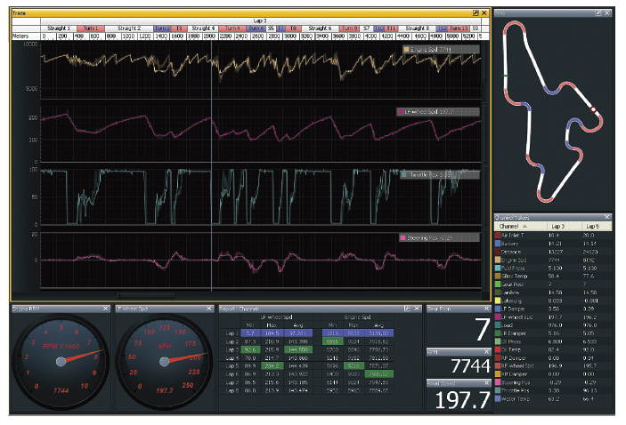
A fully customizable graphical user interface allows users to set up the display of information tailored to their personal preferences or specific tuning requirements.
Oil Pressure Sensor
The most important safety sensor on any engine is the oil pressure sensor. Nearly all ECUs can provide engine protection through a forced shutdown when oil pressure goes below a set minimum for a fixed duration. If there is only one safety sensor incorporated in your EMS strategy, it should be an oil pressure sensor.
Oil Temperature Sensor
An oil temperature sensor is a good addition for any car that will be tracked. It’s also not a bad idea for all cars as rev limiters can be set based on oil temperature to make sure that an engine isn’t revved excessively when the oil is still cold.
Coolant Pressure Sensor
Think you are lifting the cylinder head under high boost? Find out for sure by having a coolant pressure sensor as part of your EMS solution.
Engine Crankcase Pressure Sensor
Are you losing ring seal at an elevated RPM? Is your engine condition deteriorating? When a crankcase pressure sensor is part of the system, it’s possible to identify these issues and more.
Transmission and Differential Oil Temp Sensors
Usually best suited for vehicles that will be tracked, placing temperature sensors in both the transmission and differential will provide the data necessary to see if safe temperatures are being maintained for the lubricants.
Clutch Pressure
By knowing the clutch pressure, an EMS may have the ability to provide a momentary engine kill for flat wide-open-throttle shifting. The clutch pressure may also be used to activate a two-step rev-limiter.
Nitrous System Armed/Active Sensors
If the ECU will be controlling or making corrections when a nitrous-oxide system is armed or activated, the ECU needs to know that the system is active or in operation. This information is fed to the ECU on simple digital channels that simply tell the ECU if a device is on or off.
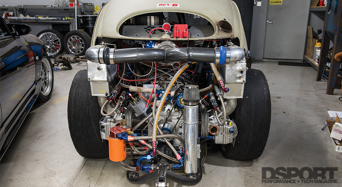
Any engine can benefit from a modern EMS solution. Follow along as we configure and setup the EMS on this VW Bug which will set its sights on setting a new world record.
Logging Sensors
There is no end to the list of sensors that can be employed upon a vehicle to log engine and vehicle parameters. While the aforementioned are the ones that are essential or related to controls executed by the ECU, there are a group of “logging” sensors that provide exceptional information for the setup of the vehicle. These sensors are too numerous to list. Some of the more popular examples are clutch speed sensors (useful for setting up slipper clutch or controlled-bleed clutch hydraulics), 3-axis accelerometers (can be used with GPS for track mapping), laser ride height sensors and shock travel sensors for suspension setup, tire-temp sensors (infra-red non-contact) and brake-temp sensors (infra-red non-contact).
Input Expansion Boxes
While some ECUs may not have enough input channels to see all that you consider important, many offer input expansion boxes that allow additional inputs to be recorded. Most of these systems convert the analog and digital inputs to a CAN signal fed into the main ECU. Do your research to ensure that the information being recorded by the expansion box can be used how you would like it to be used. Sometimes, you may only be able to log the data from these inputs without making it available to the ECU for the purpose of control strategies. Sometimes, the issues can just be averted by putting all the essential and correction sensors to the ECU while the advanced tuning sensors get fed to the expansion box. Don’t assume the obvious as many of the ECU manufacturers will configure the devices in a way that seems 180 degrees from logical to you.
The Bottom Line
While all EMS systems do some of the same things, like control fuel delivery and spark timing; they all don’t do it at the same level of performance. In addition, some EMS systems have considerably more capabilities than other systems. Worst of all, there is no universal agreed upon language for the inputs, outputs and functions of an EMS. One EMS manufacturer might refer to fuel enrichment based on how quickly you blip the throttle as acceleration enrichment, another might call it wall wetting, and another might call it accelerator pump. While there are a host of difference, understanding the input side of the equation will help to narrow down your field of choices.


