In the manufacturing of an issue of DSPORT Magazine, the speed and capabilities of the bindery at our printer represents the bottleneck. You can get faster presses to print more pages and forms per hour, and you can get more automation and labor to box and package the final magazines. But it will do no good. If the bindery can fold and bind 100,000 magazines per hour, this bottleneck sets the maximum performance level. Having a page form printing and packaging capacity beyond the limits of the bottleneck (bindery) does nothing. You will either print more pages that sit and wait for the bindery or you will have labor waiting around for more bound issues to come out for packaging.
Text by Bassem Girgis // Photos by Staff
DSPORT Issue #203
If we use a bigger jar with the small cone, it will do us no good. The jar size doesn’t make a difference unless we address the bottleneck in the cone first. The same goes for your car’s performance.
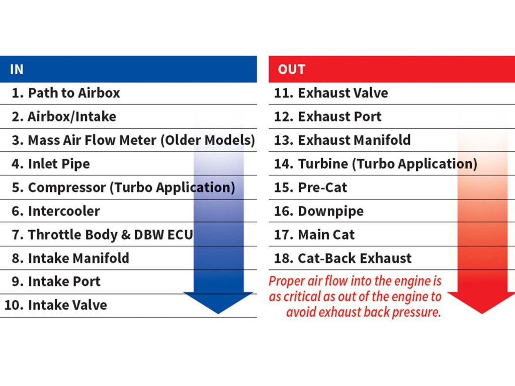
Just about any system can be broken down to highlight the bottlenecks. In the case of the above example, doubling the capacity of the printing presses or the capabilities of the packaging department may become the bottleneck. Your car’s engine can also be modeled as a staged system with multiple areas that may become the bottleneck in the system. So, how do we find the bottleneck? Some platforms have been around long enough that the proper mix of upgrades to eliminate the bottlenecks are well known to reach a desired performance level, other platforms may be too new or underdeveloped to be fully understood. On a vehicle, engine performance can be limited by bottlenecks in either the air flow or fuel delivery systems. This month, we will highlight all of the components that either affect the delivery of air into the engine or combustion products (exhaust) out of the engine.
The Bottlenecks
Engine performance is limited by how much air can be ingested by your engine. This amount of air is combined with the optimal amount of fuel to produce the maximum amount of energy through combustion. Getting more air into the cylinders allows more fuel to be burned and more energy and power to be realized.
Unfortunately, not addressing the bottlenecks first means you might be adding parts that don’t deliver more performance. These may be great parts that will add performance once the bottlenecks are addressed, but they may show no increase in performance at all with the bottlenecks in place. This is where knowledge is power and getting information from a qualified source (like DSPORT or Club DSPORT) saves you time, money, and headaches while delivering the maximum bang for your buck. After explaining the air flow goals in terms of volumetric efficiency and mass air efficiency, we’ll take a look at all of the possible locations for that bottle to increase performance.
1. Path to Airbox
Before the air even makes its way to your factory airbox, it may need to pass through an opening in the bumper, traverse a grille element, enter a duct and navigate through this duct to the engine compartment or the airbox itself. To improve this path, first take a hard look at the OEM layout. Why did it take such a path? Could the ducting be increased in size? Could the initial source for the air be taken from a cooler location? Can the number of turns and twists be reduced? If there is an opportunity to improve this path, improve it.
Although the factory airbox can be a restriction at times, it isn’t always the case with all makes and models.
2. Airbox/Intake
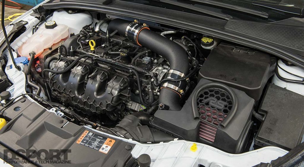
Originally designed with the purpose of simply housing the air filter in a convenient location for ease of service, the factory airbox is home to the air filter. OEM air filters generally use a paper or carpet-like media that is pretty effective at filtering out dust, dirt and contaminants when new. Over time, the filtering properties remain good but the filter itself begins to become an impediment to air flow. Upgrading these panel filters to high-performance aftermarket units will typically deliver 2-to-5 horsepower on most applications. When the factory airbox leaves much to be desired from a performance standpoint, an aftermarket intake system may deliver substantial power gains on the order of 10 to 20 horsepower. It all depends on the application. With the Honda Civic Type R and Ford Focus RS, the factory airboxes are well designed for the OEM power levels. Dyno results show barely measurable improvements with an aftermarket intake system in place. However, once the turbocharger is upgraded, all bets are off as the limits of the factory airbox at higher power levels may become obvious.
3. Mass Air Flow Meter (Flapper Models)
The mass air flow sensor measures the mass of air going into the engine. On older models, a vane type of mass air flow meter is used. This system uses a flap that opens using the incoming air. The more air is coming through, the farther back the door is pushed. Behind the first flap is another vane used for a more accurate monitoring. As you can imagine, the force needed to push the flap open works as an added restriction for the air. To eliminate the bottleneck, there may be a modern hot-wire mass air flow meter conversion available. In lieu of that option, a conversion to speed-density (eliminates the MAF all together and uses a MAP sensor to determine engine load) could do the trick.
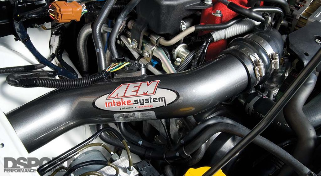
Ensuring the inlet pipe from the intake filter to the turbo or throttle body is large in diameter can free up some air and improve power.
4. Inlet Pipe
The inlet pipe connects the airbox to either the throttle body (naturally aspirated) or compressor inlet (boosted). On a naturally aspirated engine, the inlet pipe will go directly from the intake to the throttle body (perhaps including the MAF meter along the way). If you have a turbocharged or centrifugal-supercharged engine, the inlet pipe will go from the intake to the compressor inlet of the turbocharger. This pipe plays a big role in air flow. The larger its diameter, the higher its air flow handling capabilities. More twists and turns in the pipe’s design mean more air flow restriction will occur. Be sure your inlet pipe is large enough in diameter to support the amount of air needed for your target power level. Most of the time, the inlet pipe provided with the aftermarket intake system will be large enough for the application.
5. Compressor (Turbo or Centrifugal Supercharger Application)
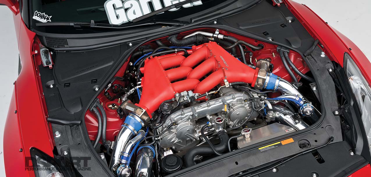
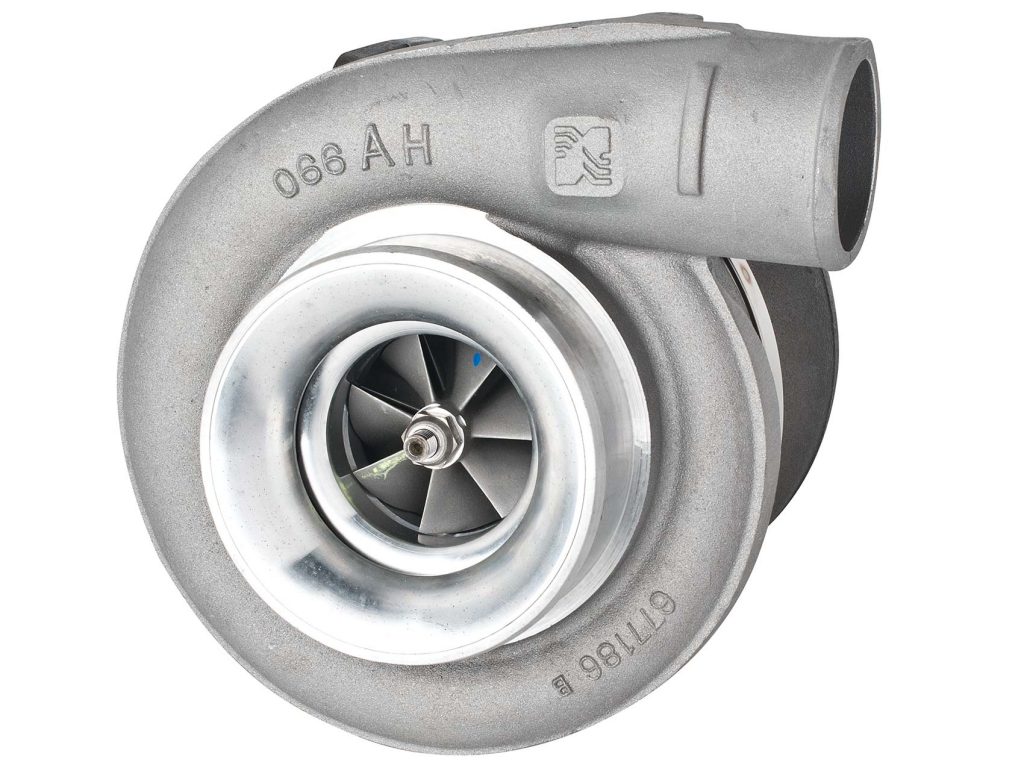
The compressor side of a turbocharger consists of a compressor wheel and compressor housing. The size of the compressor wheel and its aerodynamic design determine the amount of air flow the compressor section will provide at a given pressure ratio, shaft speed and compressor efficiency. “Small” turbos provide quicker boost response but ultimately become a bottleneck to additional power output. When a turbocharged engine can’t hold a given boost pressure to redline (regardless of wastegate’s duty cycle), the compressor section has reached maximum output. The R35 GT-R is a great example where one may realize 19-20psi of boost pressure at lower engine speeds, only to see it drop off to 15-17psi near redline.
Increasing the flow potential of the compressor side of the turbo or centrifugal supercharger with a larger wheel and housing combination will eliminate this bottleneck, but there will be repercussions in many cases. Bigger turbos will generally have reduced boost response (target boost pressure cannot be reached at lower engine speeds) while bigger compressor sections on centrifugal superchargers will require more power to be stolen from the crankshaft to be driven.
The turbocharger’s housing, compressor wheel, its aerodynamic design, and its size can be a restriction to the air flow entering the engine.
6. Intercooler & Charge Pipes
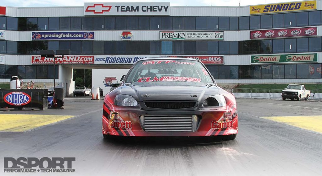
The intercooler is a heat exchanger designed to cool the charge air before it’s ingested by the engine. Its size, placement and construction (tube-and-fin, bar-and-plate) will all effect how well it performs in reducing charge air temperatures. To save weight and cost, OEM intercoolers are generally designed to be as small as possible to deliver a measurable but not necessarily optimal charge air temperature reduction at OEM power levels. Upgrade the turbo or even raising the boost on the OEM turbo and it’s easy to exceed the capabilities of the OEM intercooler. Larger aftermarket intercoolers when properly designed can provide exceptional charge air cooling benefits, especially at elevated power levels. As with anything in the intake path, the diameter of the charge pipes can also influence power output. Pipes that are too small in diameter may become a restriction to flow and limit the power output.
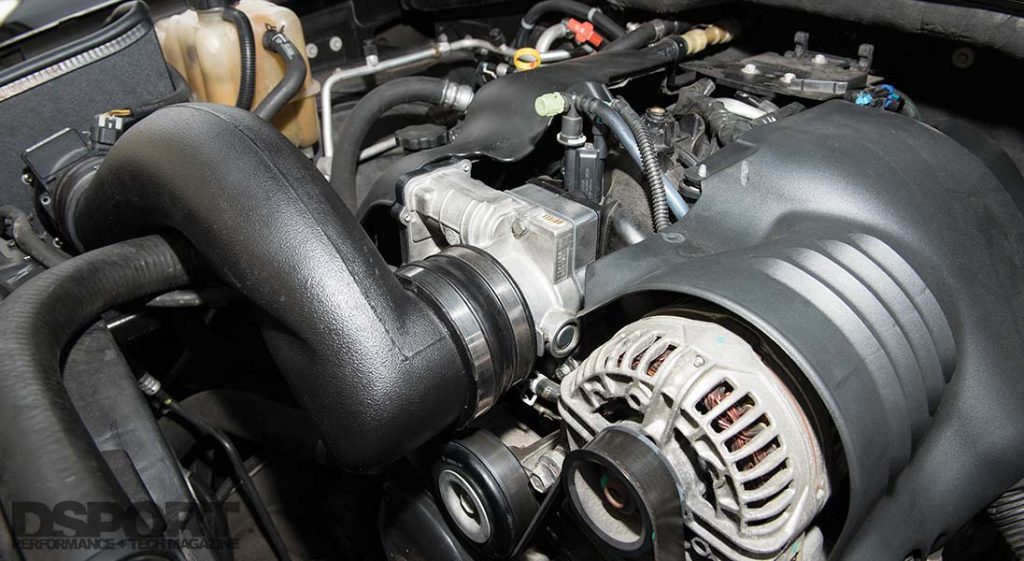
When more air (than factory) is being forced into the engine, sometimes using a larger throttle body is beneficial.
7. Throttle Body & DBW ECU
Whether it’s coming from an inlet pipe or a charge pipe, the throttle body serves as the gatekeeper of air flow into the engine itself. Before any air can enter the intake manifold, the throttle body and the position of the throttle blade itself will regulate the amount of air allowed into the engine. Up until about 15 years ago, almost all engines used a mechanical cable or linkage to put a 1-to-1 ratio between the position of the acceleration pedal and the position of the throttle blade. When the diameter of the body and the blade were smaller than optimal, some of the flow to the engine would be choked off even though the throttle blade was fully open. The remedy was to replace the smaller diameter throttle body with a larger diameter replacement. More recently, mechanically-manipulated conventional throttle bodies have been replaced by a Drive-By-Wire (DBW) throttle body, which uses an electric signal generated from the pressing of the accelerator pedal. While one might expect a flooring of the accelerator pedal to result in a complete and full opening of the throttle plate, it’s rarely the case. The position of the accelerator pedal is just one input into the ECU that “influences” the position of the throttle in the throttle body.
8. Intake Manifold
While the throttle body acts as the crossing guard in allowing air flow into the engine, the intake manifold attempts to direct an equal amount of air to each cylinder. The shape, length and taper to each of the intake runners to each cylinder will influence the behavior of the engine. The length, shape, cross-sectional area and taper to these runners will influence at what engine speeds (RPM) optimal tuning occurs. The size of the common plenum where all of the runners join also influences performance. Since the exhaust manifold, camshafts and cylinder head characteristics also play a role in determining at what engine speeds the engine will be most efficient, successful engine developers spend a great deal of effort matching these components for the desired torque curve.
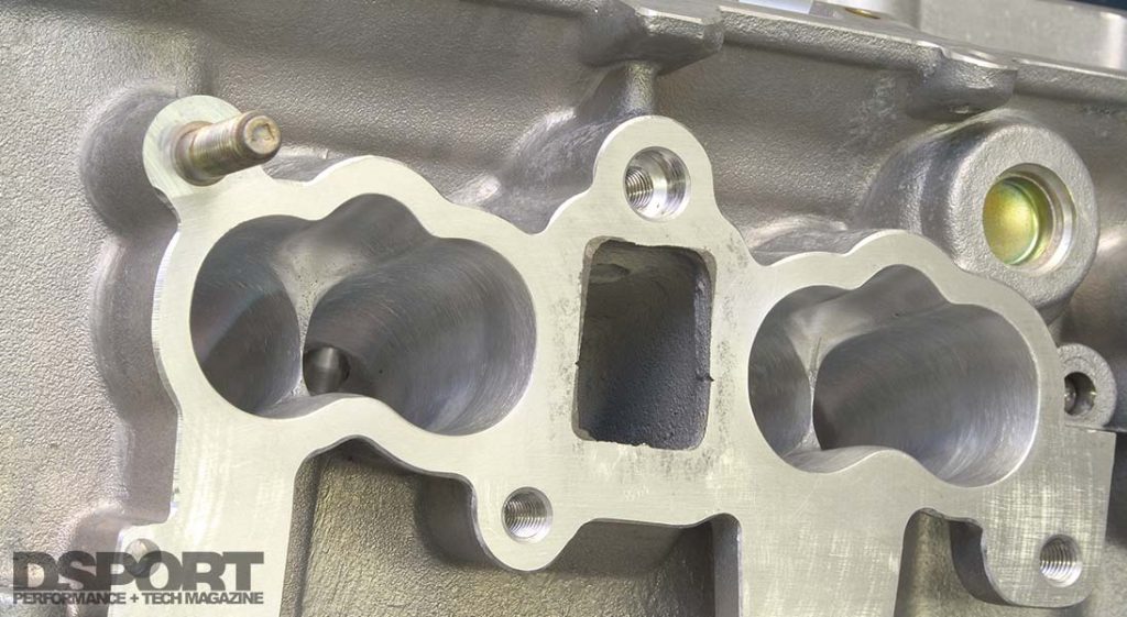
Despite being costly at times, porting the intake ports can realize more power and improve response.
9. Intake Port
The air is distributed from the intake manifold into the head. The cross-sectional area and the shape of the port make the biggest difference in air flow. That’s why “porting” cylinder heads is an extremely popular method of unlocking more power potential. The goal is to develop a port that balances flow and velocity to maximize the filling of the cylinder. This is especially critical across the “powerband” that the engine will be operating. The optimum size of the intake ports depends on engine speed, displacement, and whether forced-induction is used. During porting, careful attention has to be paid to the transition area from the intake opening to the bowl area. The shape of the port is critical. The more direct the path for the air into the cylinder the better, all other factors being equal. Like everything else, bigger is not always better. Flow numbers alone don’t even tell the whole story. Having a 10-percent increase in air flow through porting can equate to a 10-percent increase in power, only if the port is close to the optimum size and velocity of the flow has not been affected. Refer back to our “Ported & Flowed” article in issue 22 of DSPORT Magazine (or dsportmag.com) to learn how intake porting affects horsepower and throttle response.
10. Intake Valve
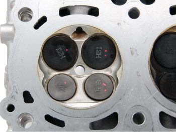 Before the air is ingested into the cylinders, the intake valves have to open to let it through. The size and shape of the valve will affect the flow through into the cylinder (especially at low valve lifts). Perhaps even more than the valve, the “valve job” will also have a major effect on head flow (especially at lifts up to 0.250” on most applications). The “valve job” refers to the angles and cuts made on the valve seat where the valve seals in the cylinder head. No matter how well the intake port in shaped, it is always a challenge to get the air to flow around the valve and through the opening between the valve and seat as it opens. The valve job will also influence reliability and longevity. Valve jobs that use ultra-narrow seating surfaces may show flow improvements, but these narrow seats may not be able to transfer heat out of the valve quick enough. This can lead to warping of the valves and damage to the seats. In a number of Japanese engines, the valve diameter is large enough or sometimes too large for the intake port itself. If oversized valves are being used, be sure that the port shape has been optimized for the larger valve.
11. Exhaust Valve
Similar to the intake valve, the exhaust valve is the route where the exhaust gases exit. Proper flow into the engine is just as important as the flow out of the engine. Any air flow restrictions on the way out can cause exhaust back pressure forcing horsepower to be wasted pumping out the exhaust. During the exhaust stroke of the combustion process, the exhaust valve opens as the piston goes up to force the exhaust gases out of the cylinders. If the air can’t flow fast enough outside of the engine, engine power and efficiency is decreased. The same approach for intake valves can be taken for exhaust valves to ensure proper air flow.
12. Exhaust Port
When intake porting is done, usually exhaust porting is done as well. This ensures that you don’t waste the power that you’ve gained from freeing the air coming into the head. Similar to intake porting, exhaust porting also increases the diameter of the ports and improves the angles of the areas where the exhaust gases hit on the way out. When both intake and exhaust ports are optimum, the engine is more efficient and more power is the result.
13. Exhaust Manifold
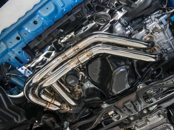 Once the exhaust gases exit the cylinders, they go through the exhaust manifold. All of the exhaust gases flowing through the manifold are collected into one pipe. Factory exhaust manifolds can create a bottleneck as more exhaust gases are forced out of the engine. The bottleneck creates exhaust back pressure, which decreases efficiency and power. Using an exhaust header is a good upgrade to reduce the amount of exhaust back pressure. Instead of forcing the exhaust gases into a shared manifold, an exhaust header gives each cylinder its own pipe. The pipes are usually the same size, which lead all exhaust gases from the cylinders into a larger pipe known as the collector. The diameter of the pipes and collector, as well as their shapes, determine the air flow potential of the manifold.
14. Turbine (Turbo Application)
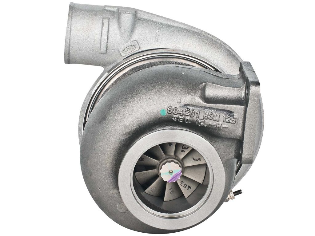
The turbine section of the turbocharger is responsible for taking the energy out of the exhaust and turning that into shaft work to power the compressor section. The hot, high-energy exhaust gases first enter the turbine section through the turbine housing. This housing is essentially a nozzle that speeds up the exhaust gases and direct them against the blades of the turbine wheel. Many applications will offer a selection of different nozzle sizes to accommodate different engine displacements and operating ranges. This nozzle size is described as the A/R ratio. Smaller A/R ratios are designed for smaller displacement engines, while larger are for larger displacement engines. The A/R ratio can also be used as a tuning tool. Using a smaller A/R ratio turbine housing will increase boost response but may choke off peak power at an earlier engine speed than a larger A/R turbine housing. The design of the turbine wheel, diameter, as well as the design of the turbine housing and its exit points influence the mass flow capacity. To ensure the turbocharger is doing its part in maximizing performance and eliminating air flow restriction, coordinating the diameter of the compressor wheel with the turbine wheel is critical.
Like the compressor side of a turbocharger, the turbine side also plays a critical role in smooth air flow for the gases exiting the engine.
15. Pre-Cat
Not all makes and models are equipped with pre-cats, but it is becoming more common on newer turbocharged vehicles. The reasoning is that it takes a certain amount of heat energy to “light off” the catalytic converter into an operating mode. By positioning it as close to the engine as possible, more heat is available than if it was positioned further downstream. All catalytic converters are designed to reduce HC, CO and NOx emissions. Each state has different regulations when it comes to catalytic converters, so be sure to check your local laws. If you are going to drive your vehicle on the streets, keep you cats in place. If you have a race-car, however, completely removing the cats will yield some gains depending on the technology used in the catalytic converter. Today’s modern cats have a much lower impact than the first- and second-generation catalytic converters found on older vehicles.
16. Downpipe
In turbocharged applications, reducing exhaust back pressure in the exhaust system after the turbine outlet will improve boost response. This means that the entire exhaust system must be as efficient as possible. Following the pre-cats, the exhaust gases go through the downpipe. The downpipe’s diameter and design contribute to their air flow characteristics. On many applications, a downpipe is either offered with cats or as a cat-less option. There are both federal and state laws regarding catalytic converter replacement. Check these before purchasing a catted downpipe with the expectation of being emission legal. Just because you put a catted downpipe doesn’t mean that you are smog legal in all states. Save the cat-less downpipes for full race vehicles.
17. Main Cat
The main cat is usually located after the downpipe. On some applications, this may be the only cat on the vehicle. Most people replace the cat-back portion of the exhaust hoping it can improve flow, but if the main catalytic converter is restricting the air flow, going with a larger-diameter exhaust won’t make much of a difference. Similar to the pre-cat, higher-flow cat (if your state allows it) or completely removing the cat for race applications will reduce or eliminate restriction before having to turn your attention to the last component that could contribute to air flow.
18. Cat-Back Exhaust
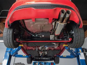 Most people replace their exhaust systems as their first attempt to increase air flow. Not only can it add performance, it looks good and it can improve the sound of the vehicle. Fortunately or unfortunately, current OEM exhaust systems are designed pretty well. This means power gains may not be as significant as older vehicles. In fact, power gains may be non-existent with this upgrade alone since it’s the last stop on the air flow bottleneck map. Factory exhaust systems aren’t always designed to realize maximum power. They are engineered to be cost-efficient while providing quiet exhaust notes for daily-driving conditions. Replacing the factory exhaust with a quality, larger-diameter cat-back exhaust can keep your car smog-legal while eliminating the last of the exhaust back pressure. Consider a large-enough exhaust that will eliminate any restrictions, but not too large that will add drone and an ultra-loud note that is unnecessary and annoying without any added power benefits.
The Bottom Line
Proper air flow is a chain that starts at the front bumper and ends at the rear bumper. While most people focus on the first or last item, the bottleneck may be one of the many components between these two. If there is a legitimate roadmap to performance upgrades for your platform, addressing the restrictions in the correct order will yield the most gain for the least bucks. In the next issue, we will address all of the fuel system bottlenecks and how you can maximize fuel flow to go with your air flow.


