
Simple answers deliver convenience over accuracy. The simple answer to why Mitsubishi’s 4G54B engine struggled to deliver serious performance while its 4G63 engine shined is usually attributed to the number of valves per cylinder. While this answer is convenient, it’s far from accurate. The number of valves per cylinder is just one aspect of a cylinder head’s design that affects performance. There are well-designed and poor-designed 2-valve and 4-valve cylinder heads. In fact, there are many 2-valve-per-cylinder engines that can deliver exceptional performance. For instance, a well-engineered big-block Chevy engine can make over 120 horsepower per liter while generating at least 90 percent of its peak torque across more than 3,000RPM. Those numbers are beyond what 4-valve 4G63 and even Honda’s B- and K-series engines in factory form ever produced. So, if it’s not two valves per cylinder, what makes the G54B cylinder head such a poor performer? To answer that question properly, I asked engine developer Allan Lockheed Jr. to break it down. Before Allan answers that question, we will first take an in-depth look at the G54B cylinder head followed by a sneak-peek of the magic being done on the G54B cylinder head by Craig Gerfen of Race Engine Systems.
By Allan Lockheed Jr. // Intro by Michael Ferrara // Cylinder Head Development Work by Craig Gerfen
DSPORT Issue #215

The Overview
The G54B cylinder head is a two-valve per cylinder design providing a single intake and a single exhaust valve per cylinder. The intake and exhaust ports are on opposite sides of the cylinder head allowing a cross-flow design. All of the intake ports are identical to each other while the exhaust ports are also identical to each other. The position of the ports matches the cylinder bore spacing across all four cylinders. The intake and exhaust ports are round and offset to the valve guides to produce a high swirl effect. The combustion chamber is hemispherical with a spark plug located in the side of the chamber pointed toward the intake valve.
Many of the OEM G54B cylinder heads feature the Mitsubishi Clean Air (MCA) Jet valves. This was a third intake valve assembly placed next to the intake valve in the combustion chamber that was designed to improve emissions. Unfortunately, it was also the cause of many cracked cylinder heads too. The aftermarket G54B cylinder heads we sourced do not have these problems waiting to happen in place.

We measured the volume of the combustion chambers, as well as the volumes of the intake and exhaust ports. This process is sometimes called “cc-ing” as the units of volume are cc.
Measuring Session
When the plan is to develop a part for increased performance, a thorough measuring session is required before any revisions are made. With the G54B cylinder head we measured the volume of the intake and exhaust ports, the volume of the combustion chamber and the cross-sectional area of the ports. We also measure the diameters of the intake and exhaust valve heads. Had the G54B been a cylinder head that needed more simple subtractive surgery, we would have considered digitizing the ports to get a 3D model. However, previous experience told us that the ultimate solution for this head would require the addition of material and major reshaping of the port geometry. Before Craig took on this part of the development, we put the out-of-the-box G54B cylinder head on our Superflo flow bench to get the baseline numbers.

The shape of the intake ports and the offset positioning of the valve guide to the runner induce a high swirl effect to the intake charge. Unfortunately, this design isn’t the best for filling the cylinders with the maximum amount of air and fuel. Instead, much of the intake charge access to the cylinder is restricted by taking its corkscrew path.
Dimensions
The intake ports measured between 97.3 and 99cc in volume while the exhaust ports measured between 94 and 98cc. The round ports featured the same 40mm diameter at the head flange to the manifolds. The intake valve measures 46mm. This gives it an identical intake valve to bore ratio as a 2.02-inch intake valve on a 4-inch bore engine. The exhaust valve measures 38mm. This is very close to the intake valve to bore ratio of a 1.65-inch exhaust valve in a 4-inch bore engine. The combustion chamber volume was measured at 73.2cc.

The engineers at Ferrea supplied us with nine different test valves to find the optimum for the final port design. Reducing the stem diameter is one way of improving airflow, but the shape of the valve head also affects low-lift flows dramatically.

The Flow Bench
In the right hands, a flow bench can be an invaluable tool for cylinder head development work. Unfortunately, the data from one flow bench cannot be compared to the data from another flow bench. The reason has to do with the variances in bench calibrations and differences arise from different testing procedures. However, when before and after numbers can be compared from the same flow bench, true progress can be measured. The head flow on the intake side was at 167cfm at 0.400” of valve lift. This is about the peak lift of the stock camshaft. Going to higher lift number, the flow continues to improve up to 178cfm at 0.600”. Since we don’t usually have any 2-valve cylinder heads on our flow bench, we can’t really say how those numbers stack up. However, we can say that the Toyota 4AG cylinder head which is the smallest 4-valve head we’ve tested, flows 178cfm at 0.400” of lift. That’s 6.6-percent better peak flow for a cylinder head that is meant for a cylinder that is only 62 percent of the size of the cylinder in the G54B. On the exhaust, the flow curve had a similar shape with exhaust flow figures that averaged 75 percent of the intake. Again, flow figures at lifts beyond the peak of the factory camshafts showed improvements with a peak of 131cfm showing up at 0.600” lift.

Respect and Disappointment
In the aftermath of 55 mph speed limits, the fuel crisis, and growing emission controls, the 4G54 engine delivered acceptable performance at the time. The engine was affordable, durable, and maintainable. But, having owned two Plymouth Fire Arrows with that 2.6-litre engine, I developed both respect and disappointment with the powerplant. The engine was widely used by many other vehicles and manufacturers, including Dodge and Plymouth mini-vans, Dodge Raider and D50 pickups, the Mazda B2600 pickup, and some Isuzus and Hyundais also took advantage of 114-137 HP available from a proven, very smooth four cylinder, emissions-certified powerplant.
Conditions Trump Design
Driving the Fire Arrows showed that weather conditions (temperature, pressure, and humidity) determined engine responsiveness and power. In spite of Mitsubishi’s MCA-Jet modification to create mixture motion and faster combustion, the burn rate in the open, shallow hemi chamber depended on atmospheric conditions for flame propagation, not combustion chamber design. As a result, the engine struggled to produce power past its peak power RPM. The breathing advantage of Hemi valve and port geometry was not exploited with the 4G54 head design. The output of the Fire Arrow engine was just shy of 110bhp at 5,200RPM. Fire Arrows were attractive, successful rally cars, so I had high hopes for the Starion and Conquest. Every feature of technology, chassis, wheels, and styling was there (and still is!). A purposeful, unique, crisply-styled, affordable, no-nonsense, sports/GT car was my impression. The addition of electronic fuel injection and turbocharging along with a promise of more performance peaked my interest.
A Test Drive Dashed those Hopes
The many variants of the 4G54 struggled to make peak power beyond 4,800 RPM, and even turbo G54B versions were very hard-pressed to make power past 5,600 RPM. The engine was silky smooth but always had a feeling of running out of steam at the higher engine speeds. Was there something off in the formula? Looking at the specs of the 4G54 engine, everything seems in order. A built engine with similar bore, stroke, rod length, valve sizes, and 10:1 compression ratio would allow naturally-aspirated performance of 210 lb-ft torque at 5,400 RPM, and 257 HP at 7,150 RPM, with safe over-run to 8,000 RPM. But with the G54B, Mitsubishi was hard-pressed to achieve that performance even with turbocharging and intercooling. After the limited success of the G54B, Mitsubishi engineers created the brilliant 4G63. Arguably one of the best four cylinder turbocharged power plants throughout its whole production lifetime. So how could the same company that built the stellar 4G63 be responsible for the lackluster performance of the G54B?
How it Came About
With engine development, it’s best to understand how and why an engine was designed by the OEM before making a plan to change it. Even the most seemingly flawed engine may have elements of design brilliance. Case in point, the Astron series of engines (includes the 4G54/G54B) developed a twin balance shaft system that Mitsubishi licensed to Porsche, Saab and Fiat. You should never bet against the artisanal craftsmanship that makes Katana swords. These works of art can cut the finest silk handkerchief in two, in midair.

The Mitsubishi A6M Zero was Imperial Japan’s most successful fighter during World War II. Its 14-cylinder radial engine featured a combustion chamber and port design similar to the 4G54 engine. Unfortunately, what worked great in an airplane didn’t fare well on the ground.
A speculative history story told what could have happened before USA’s entry in WWII, if Mitsubishi and Nakajima had collaborated with Germany on air-cooled radial engines there may have been a different outcome. Mitsubishi could have shown Germany (particularly BMW) how to build lighter, more powerful, more durable, less expensive, easier to maintain, and more fuel-efficient air-cooled, radial aircraft engines. Burning higher-octane German gasoline, those engines would have equaled the best the allies developed by War’s end.
The answer to the G54B design lies in aviation technology and the success of air-cooled, radial, supercharged, aircraft engines. These engines set milestone standards for reliability, maintainability, durability, massive torque, and flight performance in both military and commercial application. Today the 4G54 is one of the most prevalent engines found in forklifts produced in the ‘70s, ‘80s and ‘90s.
The difference in G54B performance for cars lies in different engine requirements for aircraft propulsion. Aircraft rely upon propellers while automobiles rely on wheels. A wheel and a propellor work quite differently.
How an Aircraft Propeller Works
We know how to make a ground vehicle go faster, right? We have axles attached to wheels with tires on the ground. To go faster, you make enough power to turn the axles faster. When you run out of engine RPM, you shift gears. Acceleration from a standstill is limited by tire traction. Cars have no need to maintain power at altitudes above 14,000 ft. Contrast that with aircraft flying 20,000 ft to 45,000 ft. During that ascent, temperatures drop to -40 to -80-degree F (or less), and the air pressure is between 2.0 and 4.0psia. Aircraft propellers and engines performed quite well in this environment for decades, whether in a Republic P-47D Thunderbolt, Mitsubishi Zero, B-29 Superfortress, Kawanishi N1K2 Shiden-Kai, Lockheed L-1649 Constellation, or Douglas DC-7c.
Unlike a car, aircraft propulsion is not limited by ground traction. Each propeller blade creates thrust directly. Each blade grabs as much air as possible and throws it downstream much faster than the aircraft’s airspeed. So, would a propeller [prop] with longer blades, or more blades, or running at a higher RPM create more thrust? Not really.
Prop Efficiency
Prop efficiency drops quickly when the tip airspeed of the propeller (the vector sum of aircraft airspeed and circular speed of the prop tip) equals Mach 1, the speed of sound. Faster than Mach 1, the prop makes a lot of noise, and not so much thrust. Wonderful for air shows, bad for propulsion! Unlike a wheel and tire where spinning it faster or making it taller increases speed, this isn’t the case with a propeller.
The higher the aircraft flies, the colder and thinner the air becomes. The prop needs to throw more air downstream, and/or at higher velocity, to maintain thrust. But, Mach 1 is proportional to the square root of absolute temperature. At 40,000 ft, Mach 1 speed drops about 14% from sea level 750 mph, down to 644 mph, limiting prop RPM or propeller blade length.

Simply spinning a propeller faster doesn’t necessarily increase thrust and airspeed. When tip airspeed goes supersonic, thrust is lost and lots of noise is made. Propeller speeds are kept within a narrow RPM range. Thrust is controlled by varying the pitch of the blades.
The Blades
Shorter blades and more of them allow higher takeoff RPM, so the MT company of Germany makes excellent 4, 5, and 6 blade props when there is no other option. But even these props lose efficiency as each blade disrupts airflow to the blade following it, reducing the RPM and airspeed where drag and Mach 1 losses begin.
Together, these factors restrict propeller efficiency to an RPM range narrower than a ground vehicle needs. The solution for propeller design is the controllable pitch, constant velocity prop. By increasing the pitch of the prop blades with airspeed and altitude, propeller designers have the equivalent of a CVT transmission! Thrust and efficiency can be optimized across a narrow RPM band as a function of throttle position, temperature, and air density. The important takeaway from all this is that an aircraft engine doesn’t need to have a wide powerband.
Winnie Mae (Wiley Post’s 1930 Lockheed Vega) Reaches 45,000ft Altitude in 1934
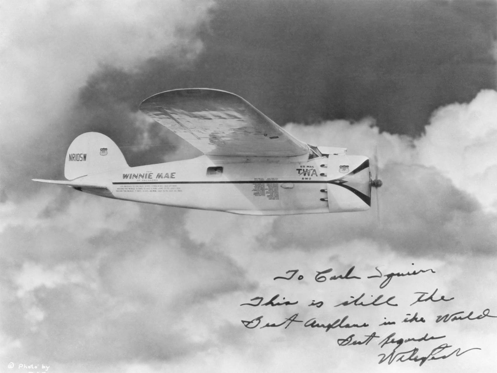
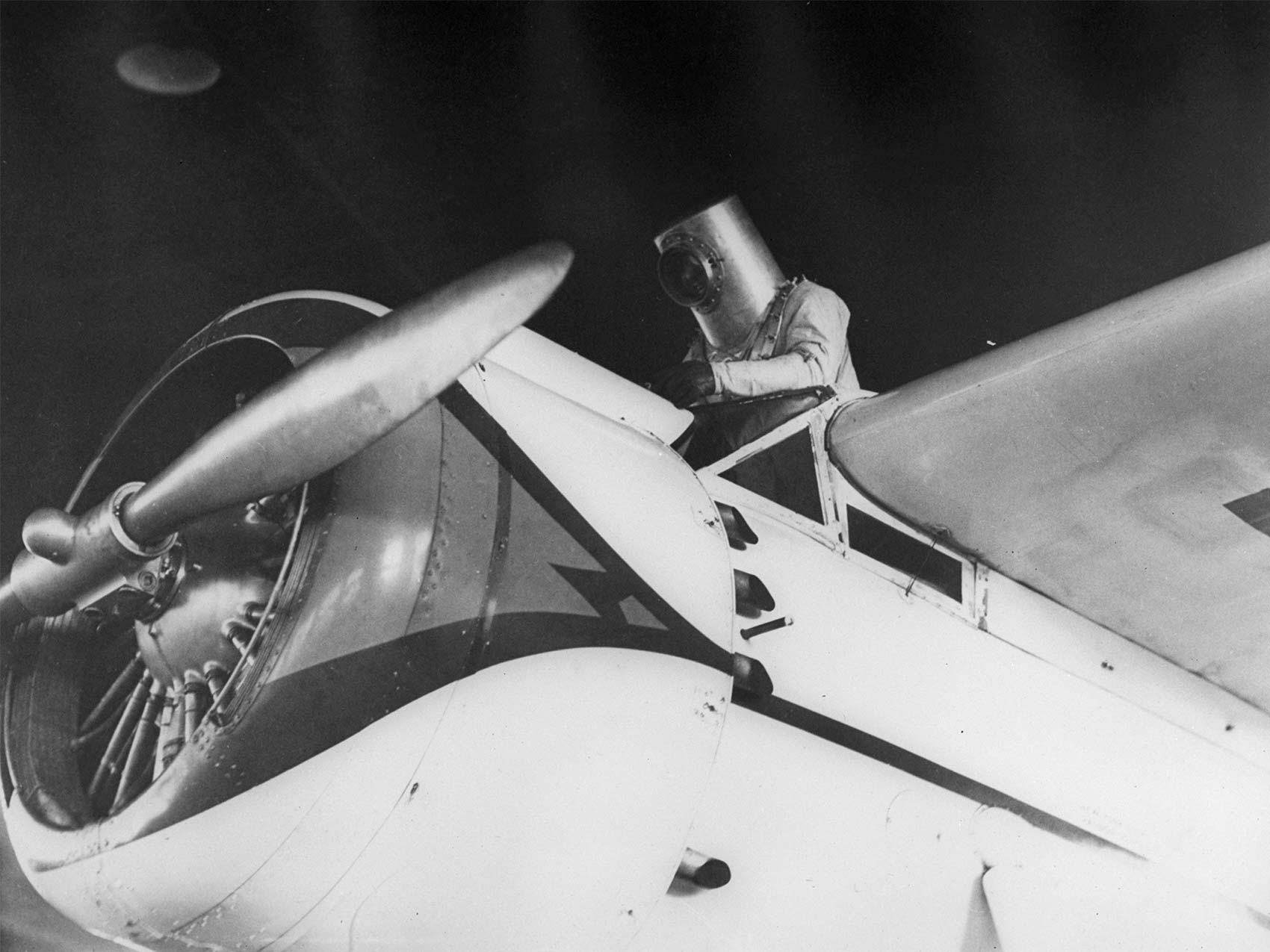
Wiley Post pioneered the solution to high-speed, high altitude flight in 1934-1935. His modified 1930 Lockheed Vega, named “Winnie Mae,” with first stage centrifugal supercharger at 10:1 drive ratio, second stage add-on Bendix Eclipse centrifugal supercharger with intercooler, controllable pitch propeller, and droppable landing gear enabled Winnie Mae to fly at -70 F above 45,000 ft. The engine was the excellent 450 HP Pratt & Whitney R-985, still in use in DHC Beaver bush planes and the redoubtable Model 18 “Twin Beech”
Air pressure and temperature at 45,000 ft is fatal, no matter how much oxygen is available to breathe. With the Goodrich Company of Los Angeles, Wiley developed a fully pressurized “spacesuit” for high altitude flight. The 3rd spacesuit design did the job. Post recorded and scientifically described the tailwind he found flying west to east, and only neglected to name it the “jet stream.” He recorded ground speed of 340 mph! As a private citizen researcher and pioneer, Wiley Post was the Neil Armstrong of his era.
What Propellers and Aircraft Need from a Piston Engine
Hanging around with Reno air racers since 2005 led to exchanging a wealth of information and insights into aircraft piston engine design and operation. Aircraft engine design standards have been applied equally to horizontally-opposed, general-aviation engines and WWII radial behemoths. Even Harley-Davidson “Knucklehead” and “Panhead” engines applied the same ideas.
WWII pushed the envelope and velocity of aircraft piston engine development to unimagined highs – in all meanings of the word! Bigger aircraft, heavier payloads, higher altitude, greater speed, fuel efficiency, easier maintenance, and over a thousand hours of durability were all required – and achieved.

2013, Reno Air Races, Unlimited Gold Final Lineup – Modified, Piston engine Race Planes
Allan Lockheed Jr Photo
Engine Displacement & Cylinders
Huge displacement cylinders of 110cid to 190cid per cylinder, arranged like a fan (radially) of 5, 7, or 9 cylinders around the crankshaft enabled massive combustion power, and provided direct air flow to cool each cylinder. Bigger engines were made by placing more rows of cylinders on a longer crankshaft, with the cylinders offset in each row so that air between cylinders at the front of the engine could be ducted to cylinders at the rear – without increased drag from greater frontal area. Two row engines of 14 and 18 cylinders were common, and the Pratt & Whitney R-4360 Wasp Major reached a zenith of 4,362.6 cid using 4 rows of 7 cylinders (= 28 cylinders, 56 spark plugs, etc…) and 3,500 to 4,300 HP and torque of more than 7,000 lb-ft to over 8,000 lb-ft at 2,400 RPM to 2,700 RPM.
Aircraft speed, range, and efficiency depend on flying high, where air density and drag are lowest. Power at high altitude and streamlining beat fuel efficiency from high compression/expansion ratio – hands down. In any case, supercharging is required to recover charge density up where the air is thin. As Mike pointed out in “Compression Ratio 101,” DSPORT issue 211, bigger clearance volume (lower compression) increases fuel – air energy in the cylinder, and permits higher supercharged density as well. Aircraft engine designers took advantage of water injection with supercharging in the late 1930s, and low compression ratios at 6.7:1-6.75:1 to add 15% VE capacity to each cylinder. Boost pressures of 45-60 in Hg raised cylinder pressure to equivalent CR of 10.3:1, up to as much as 13.7:1 with 115 octane fuel.
The ingredients of air-cooled aircraft engine performance fit the Hemi head and an undersquare bore/stroke ratio perfectly! Immediately the designer had room for large valves, a big, strong, low-compression combustion chamber, minimum internal surface area for heat loss, and lots of room externally for cooling fins. Almost the same recipe as a Top Fuel Nitro dragster uses every weekend, including dual ignition!
What was missing?
Mixture motion for rapid, complete combustion. Automotive type squish pads on piston and cylinder head surfaces don’t suit this application. Squish pads increase compression ratio, add surface area which increases heat loss, reduces strength of the combustion chamber, are difficult to air-cool, more expensive to manufacture, and weigh more. Water cooling deals with that problem, but throws away air-cooled simplicity and maintainability.
Dual spark ignition is part of the solution. Dual ignition was an aircraft engine safety requirement. But, dual ignition is an even better combustion tool. It cuts combustion time in half! Cylinder bore diameters ranged from 5-3/4” to 6-1/8”. It takes a long time for a laminar flame to cover that distance and volume. More mixture motion with turbulent flame propagation was needed. Big ports and a narrow RPM range enabled a solution – high-swirl ports.
We met high-swirl ports in Harley-Davidson Knuckleheads and Panheads, Lycoming heads, the G54B – and in a nice flowing SBChev race head that refused to perform. The flow path is like a corkscrew, does not show up in flow bench testing, and sometimes you can’t even see it. It works well where the useful power band is narrow and the combustion chamber has no squish-quench induced flame turbulence. It was the final touch in the best designs for supercharged, air-cooled aircraft engines.
Aircraft engines operate at what would only be high idle RPM for a pure racing engine. At that RPM, there is time for the intake charge to accelerate twice – linearly through and radially around – the inlet port. Then, the charge spins through the valve curtain area, maintains spin energy down to BDC, and comes all the way back up to the combustion event. With dual ignition, high swirl combustion reduced ignition advance and burned more fuel in the cylinder. The corkscrew flow path in the round port to the valve seat was engineered to provide swirl energy and cylinder filling in the limited, low RPM power band of propeller operation.

Swirl Ports… Good and Evil
As we showed in DSPORT issue 91, “Learning Curves,” automotive performance engines deliver happy driver, winning results when the RPM range from peak Torque to peak HP is at least 1,000 to more than 2,000 RPM. After peak torque, HP rises while Torque falls, and HP falls gently after peak HP for another 800 – or more – RPM. That is a big difference from a happy propeller that cares only about maximum torque across some hundreds of RPM.
The design, materials, fuel, and lubrication lessons learned from the success of aircraft engines in WWII enabled piston – propeller airliners to reach 3,500 hours time between overhaul, 136 to 189 HP per cylinder, 265 to 382 lb-ft torque per cylinder, predictable reliability, comfortable flight service, 300 to 350 mph cruise speed, over 20,000-ft altitude, and more than 5,000 up to 6,000+ mile range. Besides aircraft engines, only OTR Diesel semi-trailer truck engines run thousands of hours, at constant RPM and 65% to 100% of wide open throttle.
It makes sense that G54B variants include several 2.5-litre commercial Diesel versions, producing up to 295 lb-ft torque with aftercooled turbocharging!

The version 1.0 exhaust port is based on experience and previous head development projects. The exhaust port is moved to be more in the center of the valve placement with the roof and floor raised. The resulting shape is a “D” laying on its side.
The History of G54B
After WWII, a number of engine designers took advantage of aircraft engine technology to quickly design, develop, and manufacture durable and reliable engines. Mitsubishi took this path with the G54B by adding liquid cooling, reducing the angle between valve stems, adding some compression, deleting the supercharger, keeping the open hemi chamber, and keeping round swirl ports. The result is a low stress, rugged, large displacement engine with good torque, decent power for the time, low RPM, and narrow power range. Emission regulations required addition of the MCA-Jet valve, with related cylinder head cracking problems. Fortunately, very good cylinder heads without the MCA-Jet valve were also used, and are available for the G54B.
But, the corkscrew, round, swirl-port, flow path is the plug in the jug, and it won’t show up at normal flow bench pressures and velocities.

G54B Head
The G54B ports and combustion chamber are optimized for torque at 3,750 to 4,000 RPM. As RPM increases the cylinder pulls harder on the port, increasing radial swirl velocity in the port – rather than increasing cylinder filling through the port into the cylinder. Both the round port cross-section and the corkscrew shape accelerate swirl with RPM.
A colleague at Reno with F1 auto experience ran CFD [Computerized Fluid Dynamics] simulation for a popular engine. More than 10% of intake charge in the port would actually turn around and come back up the port at the top of the RPM band. That destroyed any power advantage of a low CR, big clearance volume combustion chamber. It also increased parasitic pumping power loss. But, it did enable ridiculously high compression ratios.
As RPM increases, swirl – unimpeded in round ports – increases the time and flow path length for air to enter or leave the cylinder. For carbureted or TBI intakes, swirl plasters wet fuel onto the port walls, and opens a hole in the center of the swirl vortex where little or no air flows. Flow loss increases approximately as the square of RPM.
For an open combustion chamber and a narrow power band, carefully engineered port swirl is a great tool. Otherwise, a high velocity, NOT round port with just enough flow rotation at the valve seat to distribute fuel and air evenly through the valve curtain area – plus combustion chamber with squish pads – is the winning design strategy for ground vehicles. Stay tuned as Craig shows us how this is done in part two next month.
