
Optimizing an engine’s compression ratio for the type of fuel and the boost levels (forced induction applications) that will be used can result in additional power, increased torque and improved fuel economy. As you may already be aware of, some engines are optimized from the factory to run on higher-octane grades of gasoline (PREMIUM ONLY). These engines will generally have a higher compression ratio than a similar engine designed to run on regular grade gasoline. If you are going to be upgrading to a “built” engine in the future, you will have the option to change your compression ratio. To help you make an educated decision, DSPORT will be doing a three-part series on Compression Ratio 101. In part one, we will define compression ratio and all of the math needed to calculate the actual compression ratio of an engine (often different from the manufacturer’s spec). Part one will also talk about all the various methods available to change the compression ratio. In part two, we will explore how fuel octane, ethanol percentages, boost levels and types of driving will factor into selecting the ideal compression ratio for a particular application. Finally, in part three, we will explore the ways to reach the ideal compression number that lead to maximized combustion efficiency. So let’s get started with a look at exactly how compression ratios are calculated.
By Michael Ferrara
DSPORT Issue #210

Static Compression Ratio
An engine’s static compression ratio, usually just referred to as the compression ratio, is a function of the engine’s “swept” and “unswept” cylinder volumes. The swept volume represents the dynamic volume of the cylinder based on the pistons position when at its lowest (Bottom Dead Center or BDC) and its highest (Top Dead Center or TDC) position. The swept volume of a cylinder is the same as the displacement of the individual cylinder.


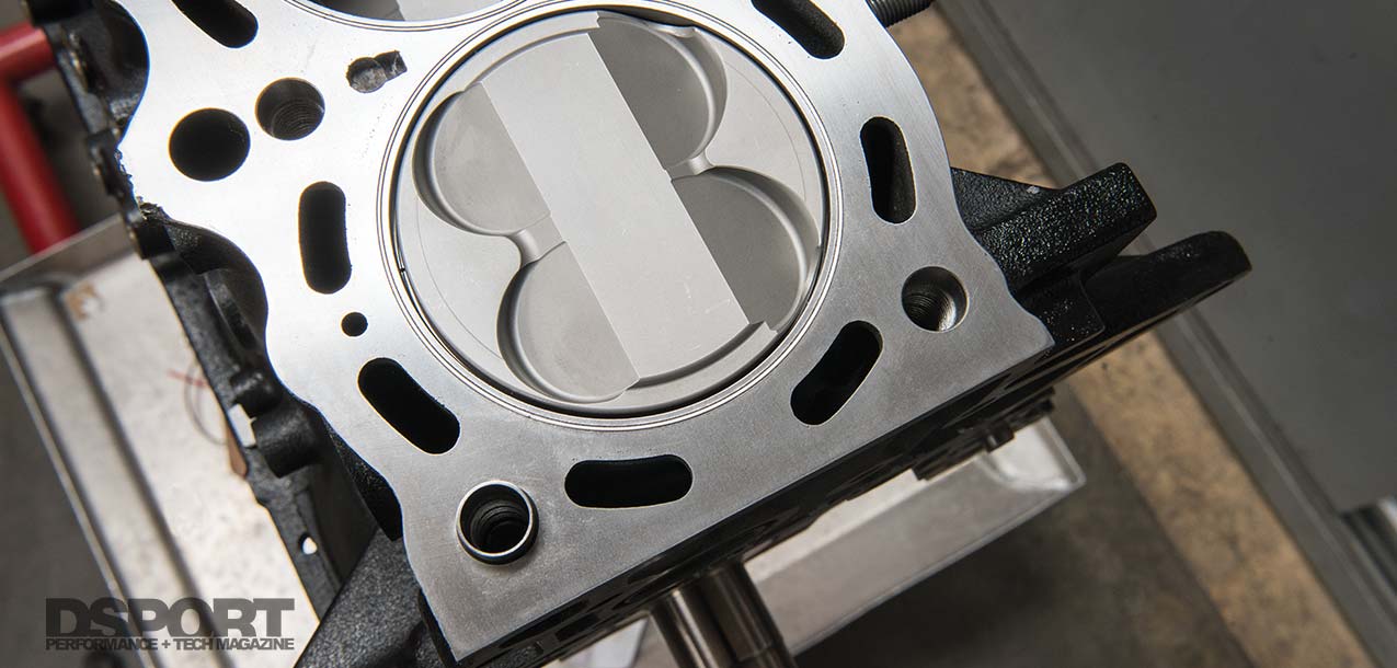
Head gaskets are usually 0.5mm to 1.0mm larger in bore size than the cylinder they will seal. If the manufacturer doesn’t specify the gasket bore size, a set of calipers can be used to make a direct measure.
The unswept volume of a cylinder is the volume of the cylinder that doesn’t change. This volume is made up by the volume of the combustion chamber in the cylinder head, the volume created by the head gasket, volume added or subtracted by the piston crown (domes, dishes, valve reliefs, fire slots) and the volume added or taken away by the piston-to-deck position with the piston at TDC.

Swept Volume
Calculation for the Swept Volume (cc) of an engine is quite simple as it is equal to the displacement of a single cylinder:

If the total engine displacement is unknown, but the bore and stroke is known, this equation can be used instead:

Unswept Volume
As previously mentioned, the unswept volume of a cylinder is made up by the volume of the combustion chamber in the cylinder head, the volume created by the head gasket, volume added or subtracted by the piston crown (domes, dishes, valve reliefs, fire slots) and the volume added or taken away by the piston-to-deck position with the piston at TDC. Unlike the swept volume calculation which can be made with simply knowing the bore and stroke of an engine, the unswept volume requires considerably more information. Some of this information can only found by a direct measurement.

Using a deck bridge fixture with dual dial indicators is the only way to get an accurate measurement. The dual indicators show if the piston is rocked to one side instead of its neutral position.
Combustion chamber volume can be measured directly by “cc-ing” the combustion chambers. This can be done with economy kits that start at about $20, or more accurate kits that run around the $120 mark. Knowing or measuring the bore size of the head gasket (it’s usually, but not always, 0.5-to-1mm larger than the cylinder bore size it’s intended to be used on) and its compressed thickness will allow the volume created by the head gasket to be calculated. Many times, these numbers are supplied by the gasket manufacturer. Always, be sure to check if the specified bore size with the gasket is for the gasket bore or the intended cylinder bore size. As for the volume created or taken away by the shape of the piston crown, this is a specification supplied by the piston manufacturer. Finally, the piston-to-deck measurement is made by using a deck bridge and dual dial-indicator setup. Once this distance is measured, the volume added (if the piston is below the deck surface) or subtracted (piston above the deck surface) from the unswept volume can be calculated using the same basic equation used for the head gasket calculation. The only difference is the possibility that this will be a negative result if the piston is above the deck surface.

Combustion Chamber Volume (cc): While you may be able to find a specification somewhere on the internet for a combustion chamber for a particular engine, chances are it’s going to be off from the actual volume of the cylinder head(s) being used on your engine.
Piston Crown Volume (cc): If the crown of a piston is flat with no valve reliefs, this value would be zero. Now here is where things get a bit tricky. For the purpose of the equation, we are trying to determine how the piston crown affects the unswept volume. If the crown of the piston has valve reliefs, a dish or inverter dome geometry, this value must be considered positive (although the piston manufacturer may write it as negative). In this way, it will add to the value of the unswept volume. If there is a dome on the piston, this value will be negative (although the piston manufacturer may write this as positive). In this way, it will reduce the overall unswept volume.

While a difference of 2.4cc may not seem that significant, it’s enough to drop the compression ratio on an RB26DETT from 8.7-to-1 (1.1mm gasket) to 8.4-to-1 (1.5mm gasket).
Volume of Piston-to-Deck Clearance (cc): The equation used to calculate this volume is nearly identical to the one used to calculate the volume of the head gasket. For this equation, we are interested in the depth into the bore that the piston sits. If the piston crown is flush with the deck, this number will be zero. If the piston is down in the bore, this number will be positive. If the piston sits above the deck, this number will be negative.
Volume of Piston-to-Deck Clearance (cc):
Example for 86mm bore with piston 0.010” below deck:
86 x 86 x 0.010 x 0.01995 = 1.48cc
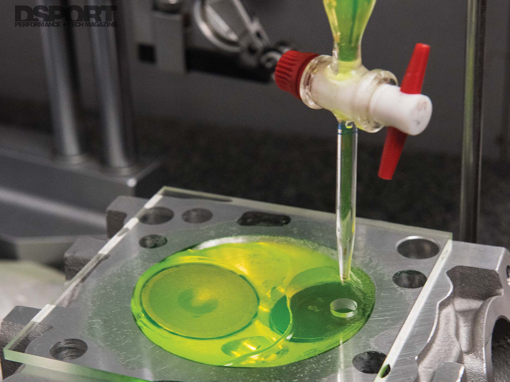

(L) A quality kit to measure the volume of the combustion chambers will include a burette. The lower cost kits will use a graduated syringe. Both kits will include plexiglass. (R) If the manufacturer doesn’t supply a value for the thickness of the head gasket when compressed, a micrometer can be used. Be sure to measure an area that has all of the layers, but avoid measuring the stopper/folded layer.

Actual vs. Advertised Compression Ratio

When a piston is at Bottom Dead Center (BDC), the total volume of the cylinder is the swept volume, the contribution to volume from the piston, the head gasket volume, the cylinder head volume and the deck clearance volume. This is the swept plus unswept volume.
So, you purchased a set of 9.5-to-1 pistons for your engine build. That means that the compression ratio of the engine will be 9.5-to-1, right? Maybe, but probably not. It will likely be somewhere between 9.0-to-1 and 10.0-to-1. The reason is that the advertised compression ratio assumes that the combustion chamber is a certain volume that a certain head gasket is being used and that the piston-to-deck height is a specific number. The reality is that combustion chambers are cast and may be as much as 3cc larger or smaller than assumed. The deck of the cylinder head is usually cut when an engine is machined and when aftermarket valves are used, volume may be added or subtracted compared to the OEM valves. If you want to find out the actual compression ratio for your built engine, you have to take the time to have it measured. This could add an additional $200-$300 in assembly time or more to your engine build as the right way requires some mock up assembly. However, knowing the real numbers is a must when developing an engine program for maximum performance. In part two, we’ll show you the way to select the best compression ratio for maximum performance. Stay tuned.
