
There is nothing more frustrating than being part of a two-man team where you are doing more than half the work. When subtle hints don’t get the lazy half up to speed, the end result can be a very vocal argument. Each of the turbos on a twin-turbo engine feel the same way. When the work is unbalanced between the two turbos, you may even hear the turbos arguing (in the form of compressor surge). Fortunately, twin-turbo engines that utilize actuator-type integral wastegates (with adjustable rods) can be “synched” to provide similar wastegate performance from each turbo. After outlining the operation of the adjustable actuator and how it impacts performance, we will outline the synching procedure as done on our Project Time Capsule R34 GT-R.
By Michael Ferrara
DSPORT Issue #184
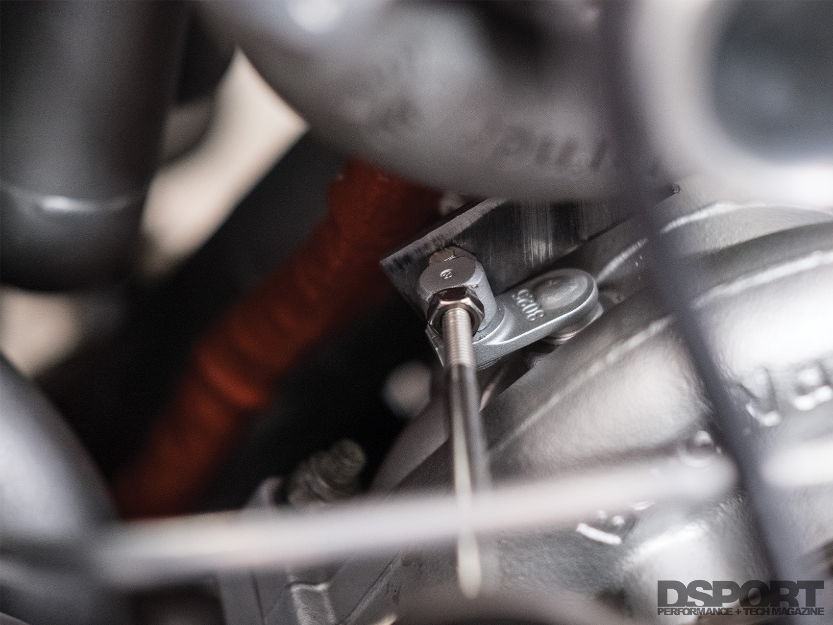
Sometimes the location of the turbocharger limits accessibility to the actuator for measurements. Using a small strip of rigid steel attached onto the end of the rod can make measurements easier.
Actuator Wastegate
To reduce cost and complexity while minimizing package size, almost all OEM manufacturers use turbochargers that feature an integral-wastegate (flapper valve) in the turbine housing that is controlled by a pneumatic actuator and rod. This configuration was once thought of as inferior to external wastegate systems due to issues that plagued earlier designs. However, high-quality modern turbochargers use superior materials in the turbine housing so cracking on the internal valve seat from thermal stresses is rarely an issue today. Since space in the engine compartment is always at a premium on newer vehicles, many aftermarket companies have started building turbo systems with integrated wastegates to reduce cost, complexity and package size. When the turbocharger with integrated wastegate is properly suited for the application, there isn’t a performance tradeoff versus an external gate when the actuator is properly tuned. High-performance aftermarket actuators allow for increases in base boost pressure and some even allow different spring combinations to be employed to change the base boost level.
Displacement & Boost
While the design of the turbocharger can play a small part in determining how much wastegating is needed, the size of the engine and the targeted boost level play a major role. The larger the engine’s displacement and the lower the boost level, the higher the demand for wastegate flow as a greater amount of exhaust flow is channeled away from the turbocharger in either case. If you are running a small displacement engine and you are running higher boost levels, the demand for wastegate flow will be minimal. Considering that we have only half of a 2.6-liter engine feeding each turbo (1.3L per turbo) and that our boost levels will be on the high side (25-30psi range), we will only be directing a small percentage of our exhaust flow through the wastegate.
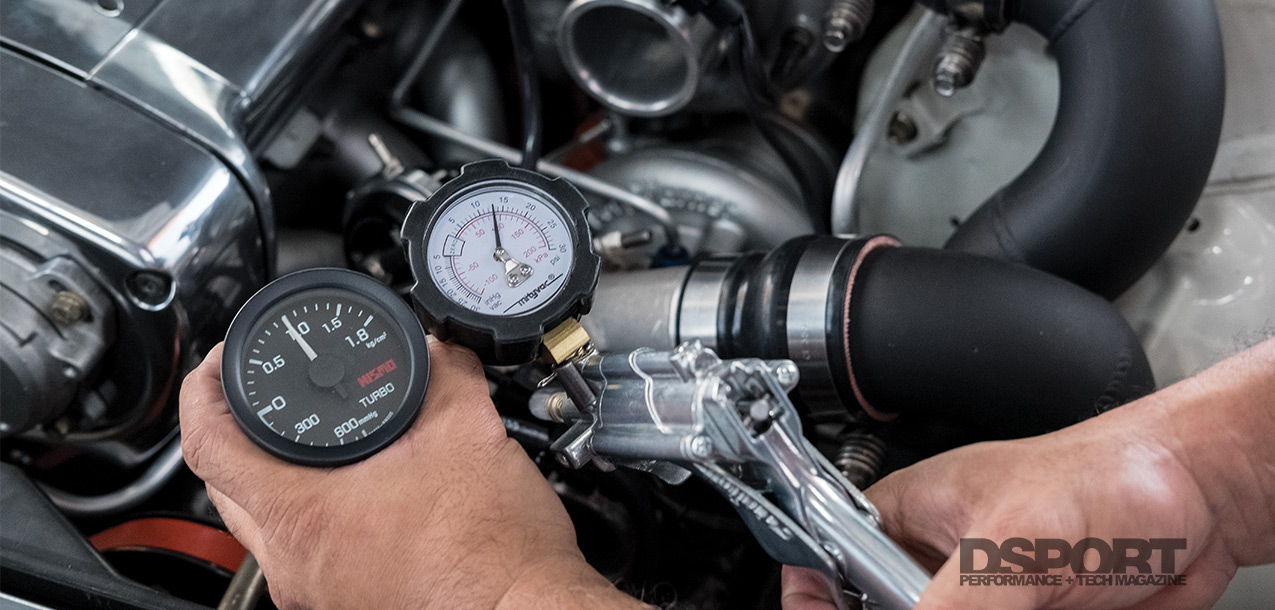
The Tools
The tools needed to synchronize the wastegates include the wrenches needed to adjust the actuator rod, a pressure pump, a pressure gauge (mechanical) and calipers or a dial-indicator to measure stroke. A handheld pump/gauge combo from Mityvac that can read up to 30psi worked well for us. If the engine is in the vehicle, you may need to make some measuring extensions to allow for quicker measurements. You will also need a notepad and pen to write down the measurements.
While a dial indicator is generally more accurate and easier to use for stroke measurements, it will be more difficult to fit in most engine compartments. As a result, a digital caliper might be the only option. No matter the measuring tool, make sure that your setup allows for repeatable measurements with loss than 0.002” of error if possible.

Stroke
Before we outline the procedure to synchronize the actuators on twin turbos, it’s important to understand the impact that each adjustment makes and why you may want to consider upgrading to an adjustable aftermarket actuator. The rod adjustment on the actuator impacts two variables: total stroke and valve-to-seat preload. Shortening the effective length of the rod decreases stroke and increases the valve-to-seat preload. Increasing the length does the exact opposite.
The amount of available stroke impacts the amount that the valve will rotate off its seat. According to Borg Warner, the EFR 6258 turbos used on our Project Time Capsule R34GT-R require about 17mm of stroke if 100-percent of the maximum wastegating is needed. As previously mentioned, we won’t be needing maximum wastegate flow due to the engine’s small displacement and the higher boost levels targeting. As such, we decided to target a stroke of about 5mm. According to data provided by Borg Warner, at 5mm of maximum stroke the 0.64A/R housing will flow about 40 percent of the maximum possible at the max stroke (17mm). This should be more than enough for our application. If we are wrong and there isn’t enough stroke, we will see boost creep (boost levels rising above the control target at high engine speeds). For more typical applications, it’s better to start off with enough stroke to allow for 70 percent of maximum wastegate flow. On these turbocharger, that would equate to about 11mm of stroke.
Preload
So what’s the problem with just setting up for maximum stroke even when 100-percent of maximum wastegate flow isn’t needed? When the actuator rod is adjusted to be longer than needed (allowing for more stroke than will ever be utilized), the amount of seat pressure or valve-to-seat preload on the flapper valve is reduced. Less preload on the valve increases the likelihood that exhaust backpressure will push open the valve. In the case of this turbo, the valve port is 31mm in diameter or about 1.17 square inches in area. This means that if there is 10psi of backpressure in the exhaust manifold, then 11.7 (1.17in2 x 10psi) pounds of force is trying to force open the wastegate. If there isn’t enough preload acting against this force from backpressure, the wastegate will open prematurely and boost response will suffer.

The preload nut must be loosened before the adjustment nut is tightened or loosened. Tightening the adjusting nut will increase preload and potentially improve response. However, it also reduces the total stroke and may lead to boost creep on certain applications.
Upgraded Actuator
For this application, we selected a Turbosmart IWG75 actuator specifically made for the Borg Warner B1 single scroll turbine housing (TS-0620-1143). This actuator comes set up at 14psi, but there are 18 different combinations of varying the two types of outer, middle and inner springs to set the desired boost pressure at 18 steps between 3psi and 26psi. Since it is a dual-port design, it is well-suited for applications where exhaust back pressures are high. When teamed with a boost control solenoid that is properly plumbed, the dual-port design accomplishes this by not allowing a pressure differential to be seen at the actuator until the target boost pressure is reached. In contrast, a single-port design has boost pressure acting on the diaphragm at all times. The result of this pressure acting on the diaphragm plus the effects of a high exhaust backpressure can result in premature opening of the wastegate.

Here’s a look at the inners of a Turbosmart adjustable single port actuator. Dual-port actuators will have a second vacuum/boost signal port placed below in the lower housing.
We opted to leave the 14psi springs in place and not order the optional springs to increase the base boost pressure. This was done so that we could run 14~17psi on 91 octane fuel. Had we planned to only run on E85, we would have likely added a 5psi inner spring (p/n TS-0505-2002) to increase the base pressure to 19psi.

The Goal
At the end of a successful attempt at synchronizing a pair of actuators, both actuators should respond with similar strokes to a boost pressure that is about 10 or 15 psi higher than the rating of the actuator spring. In our case, we checked the stroke at both 25 and 30psi to meet this requirement.
Setting/Measuring the First Actuator
After determining the amount of preload/stroke that will be required on your application, you can make your initial setting on the rod. This is simply a guess that will be verified through measurements.
Step 1: If using a dial-indicator that can measure up to an inch of travel, position the dial-indication in line with the actuator rod. Ensure that there is at least 0.020” of preload on the indicator and zero the dial. If using a digital caliper you will need to measure the length from the base of the actuator to the location of the swing valve. Making a simple measuring extension by drilling a small hole in a piece of flat stock will be necessary in many cases.

Step 2: Attach a pressure pump and gauge (we used a Mityvac Silverline Vacuum/Pressure pump with integral gauge) to the top port of the actuator. Use the pump to set the pressure at 5psi. If you are using a dial indicator, you may see the indicator dial move in the range of 0.001~0.003”. This number indicates the amount of stroke at 5psi. If you are using a digital caliper, you need to take the measurement at the same locations as step one and record them. In many cases, you may not be able to see the small 0.001~0.003” movement. Do not worry, when this process is repeated at higher pressure levels, the differences in stroke will be easier to measure. The amount of stroke will be the difference in the rod length at rest (0 psi) and at the test pressure 5, 10, 15, 20, 25, 30 psi).
Step 3: Record the stroke attained at 5psi and repeat the process recording at higher pressures (in our case 10, 15, 20, 25 and 30 psi). DO NOT exceed the recommended pressure rating of the actuator or damage may occur to the diaphragm inside the actuator.
Step 4: In reviewing the measurements, you will see that the amount of stroke barely increases at each 5 psi increment until you reach about 7~10psi above the base boost rating of the actuator. In our case, we didn’t see dramatic movement until we got above 25psi.
Step 5: Repeat and record the stroke measurements at the highest pressure level that you tested three times to establish an average number that will be targeted on the second gate.
Setting/Measuring the Second Actuator
With the first gate set and the stroke recorded at different pressures, it’s time to adjust the preload on the second wastegate to mirror the first actuator. Depending on the placement of the turbochargers and the access to the actuators, it may be advisable to tee the pressure into both actuators at the same time. This isn’t necessary, but it will allow an additional comparison.
Step 1: Repeat the Step 1 process used on the first actuator. If using a digital caliper, do not assume you can skip this step. This measurement is not going to be the same as the first actuator, so it must be recorded to get accurate measurements of the stroke.
Step 2: Pressurize the second actuator to the highest pressure value used when recording the stroke on the first actuator.
Step 3: Measure the amount of stroke and compare it to the average stroke recorded from the first actuator. If the numbers are not within 0.010” of each other, the rod on the second actuator will need to be adjusted
Step 4: If the stroke on the second actuator is more than the first actuator, the effective rod length will need to be shortened. Conversely, if the stroke on the second actuator is less than the first actuator, the effective rod length will need to be lengthened. To adjust the rod, you will need to loosen the locking nut (nut closest to the actuator) before tightening (to make the rod shorter) or loosening (to make the rod longer) the adjusting nut. The amount of adjustment needed will depend on the amount of difference in stroke. If the difference is over 0.040”, a complete turn of the nut may be required. Once the rod length has been changed, tighten the locking nut.
Step 5: Measure the amount of stroke and compare it to the average stroke recorded from the first actuator. If the numbers are not within 0.010” of each other, continue adjusting the rod on the second actuator and measure the change in stroke until the stroke is within 0.010” of each other.
Step 6: RECONNECT THE SIGNAL LINES TO THE UPPER PORT ON EACH ACTUATOR!!!!
Step 7: Verify that the boost pressure is being properly controlled with the boost controller set to its lowest setting (wastegate only). If the boost pressure is hitting more than 3psi over the rating of the actuator, you may have insufficient stroke (too much preload). If the boost creeps up at high engine speeds, you may also have insufficient stroke (too much preload). In either case, increase the rod length by a halfturn of the adjusting nut until the issue is solved.


