
Click Here to Read Our 101 Guide to Understanding the Valvetrain
Control the flow in, seal the Cylinder during compression and combustion then expel the exhaust and repeat. An engine’s valvetrain is responsible for establishing the exact timing and magnitude of each of the four cycles. The camshaft(s) and the cam lift and timing controls (where employed) conductor the orchestra. While these conductors are usually the focus of performance editorials, we decided to save that topic for another time. Instead, we wanted to focus on the players in the orchestra. These are the basic components that have simply evolved over the past century. Understanding the fundamentals of valves, valve springs, retainers, locks, seats and guides is critical to choosing the right parts that will thrive and survive in your street or race vehicle.
By Michael Ferrara, Photos by Staff & Manufacturers
DSPORT Issue #153

Direct acting overhead valvetrains are the preferred design for competition use. However, there are some proven OEM systems that incorporate rockers, followers and hydraulic lash adjusters. These are usually fine until extreme engine speeds.
The Ideal Valvetrain
While there will always be limits, it’s important to explore an ideal valvetrain to have an understanding of what valvetrain manufacturers are targeting. The main player in any modern valvetrain is the valve. Known as a poppet valve, the basic design dates back to steam engines of the late 1700s. Of course, the demands and challenges of today’s engines push the limits of metallurgy and design. The ideal valve requires a “supermaterial” that can survive having it’s face literally in the fire while being pushed, then sprung back to its seat thousands of times per minute. To top it all off, the material and design of the valve needs to be as light as possible so that control can be maintained with minimum spring pressure. As for the springs, a material and design that can provide performance over millions of cycles is a must. Valve guides must be able to provide proper stem positioning and oil control, as well as heat transfer from the stem. The valve seat must be able to seal with the valve head and not recess. These are far from easy tasks, but they are often taken for granted.

Compatibility is a must for valvetrain components. One way to ensure compatibility is to get as many of the components as possible from the same source. Springs, spring seats (when used) and spring retainers are best purchased from the same source. The same goes for valves and valve locks.
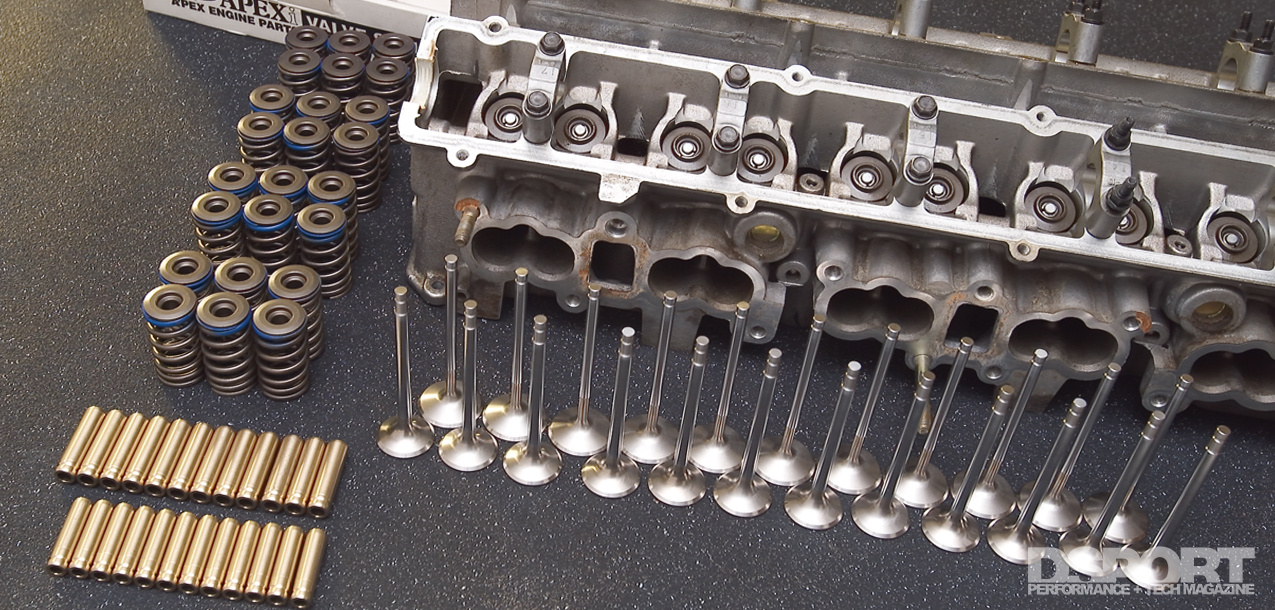
Valves
Currently, performance valves are manufactured from several different materials. These materials include a variety of stainless steels, titanium alloys and high-nickel (Inconel) alloys. Because of the extreme pressures, temperatures and forces encountered, valves need to be strong and resilient. In addition, there are benefits to having valves that are lightweight. High-power race applications sometimes choose titanium valves due to their lightweight and strength. Until recently, titanium valves were deemed inappropriate for street applications because of durability issues. Now, new coating technologies have some OEMs building factory engines with titanium valves. In the next five to 10 years, we should see the popularity also increase in the aftermarket. Currently, stainless steel alloy is the most common material used in valve manufacturing. As with any alloy, not all alloys are created equal. Some alloys will have better performance characteristics than another. In addition to stainless steels, high-nickel alloys, often referred to by the brand name Inconel, are a popular material for exhaust valves. These high-nickel alloys are extremely heat resistant. Some manufacturers coat the valve stems with chrome, black-nitride or PVD coating to reduce friction.
A valve can be broken down into three sections: the tip, the stem and the head. The tip of the valve is where the valve spring retainer is joined to the valve stem. A retainer lock secures the retainer to the tip of the stem. The tip of the valve sustains every impact applied by the cam lobe in addition to spring pressure to return the valve to the closed position. To ensure valve tip durability, manufacturers apply special heat treatment to the tips of the valves. In some cases, such as titanium valves, the tips cannot be hardened enough. Hardened steel lash caps are used in these special instances.
The valve stem is the body of the valve, joining the tip and the head. For high-rpm applications, it is often important for the valve to be as light as possible. This is because the valve must open and close repeatedly. Valve springs close the valve while the cam lobe dictates when they open, how long they open, and when they close. To make the valve light and durable, manufacturers have looked to many advanced manufacturing techniques. Space-age alloys are available, but only practical on certain applications. Stainless-steel alloys have been chosen frequently for cost effectiveness and durability, but stainless-steel can weigh more than other more exotic materials. To offset the weight, some manufacturers have chosen to hollow out the stem. In addition, some fill the hollow stem with sodium to help dissipate heat while maintaining the benefits of a lighter overall weight.
The last component of the valve is the head. There are different head shapes and materials. The head shape is important because air must flow over its backside when entering and exiting the combustion chamber. Valve heads are sometimes swirl polished to facilitate greater airflow around the head. The neck of the valve stem is the point at which the head meets the stem. A standard valve stem is a uniform diameter from the tip to the valve-head. Another technique for reducing valve weight as well as increasing the air flow characteristics of the valve is called undercutting. When a valve is undercut, the diameter of the neck is reduced to further lighten the valve and allow more air volume behind the valve-head.
Plus-Sized Valves
 Setting up a cylinder head to use oversized valves is a common upgrade. However, don’t expect oversized valves to improve flow without additional head work. While simply installing larger valves with a proper valve job may increase flow on a few cylinder heads, many cylinder heads will need “porting” on the intake and exhaust ports to take advantage of the larger valves.
Flowing versus Filling
Big valves and big ports may allow for some great peak flow numbers on the flow bench, but they may also reduce performance. Flow velocity is more important to performance than port flow, so do not get caught up in flow numbers if you don’t also have flow velocities. Having a 10-percent increase in flow numbers with a 5-percent drop in flow velocity will result in no power gains and perhaps a power loss instead.

Blending the chamber around the valve is key to maximizing efficient flow from the cylinder head. The face of the valve is usually flat or dished. Flat profiles maximize compression ratio while dished profiles minimize valve weight.
Springs & Retainers
 Valve springs represent one of the most stressed components of an internal combustion engine. For example, when an engine is cruising at 3,600 rpm, each spring is being compressed and released over 100,000 times every hour. The most basic function of the valve spring is to return the valve back to its closed position on the seat after the camshaft (and follower assembly in some cases) has opened the valve to its peak lift. The valve spring must also have enough pressure to keep the proper amount of contact force between the camshaft and follower assembly on both the opening and closing travel of the valve. Seat pressure refers to the amount of force stored in the spring assembly when the valve is completely closed. This force is achieved by reducing the spring height from its relaxed uninstalled length to an “installed” height. This installed height is measured from the base of where the spring is seated to the underside of the valve retainer once it is locked onto the valve. In most cases, spring manufacturers will specify a specific “installed height” for their spring sets. Setting the height taller than the specified length will reduce seat pressure. Setting the installed height to a measurement that is shorter than recommended will increase seat pressure. In addition to seat pressure, the installed height will also play a factor in the maximum allowable valve lift before coil bind occurs. Coil bind is a situation that is to be avoided. Coil bind can result in significant valvetrain damage as moving parts cannot travel without interference. The bottom line is that the springs that are selected for a particular camshaft must provide enough travel for the maximum lift of the cam. The valve springs must also supply the correct pressure to prevent the valve from bouncing on the seat when closed and enough “valve open” pressure to control the valve during its travel from closed to open and back to closed.
For certain engine applications, there may be a variety of valve spring options. Sometimes the options include single, single with damper, double and double with damper springs. The critical factor in purchasing the right springs means knowing the spring requirements of the camshafts being used. Additionally, if you are running high-boost pressure you may want to let your spring supplier know. Sometimes this will require a shortened installed height for additional seat pressure or a stiffer set of springs (to ensure the manifold pressure doesn’t force the valves open early).
 As for spring retainers, strength, weight and fit are the main considerations. First, a retainer of adequate strength must be selected for the spring pressures that will be encountered. Aluminum alloy retainers are most often used on lower-pressure spring setups. Steel and titanium alloy retainers are used on higher-pressure setups. Titanium retainers have proven to be tough enough for competition and high-mile street use while offering the lowest weight. They represent the best choice for nearly all applications. Steel retainers are a cheap but tough alternative. Aluminum retainers should be avoided for serious performance applications.
The weight of the retainer should be minimized when this fits into the budget. Lightweight retainers reduce the tendency of the valvetrain to enter into a valve float condition. Finally, make sure that the retainer provides the proper fit with the spring and with the valve lock assembly. If the wrong fit occurs, you may drop a valve into the cylinder and cause thousands of dollars in damage. If you aren’t sure if something fits, asks the manufacturer. It’s also a good idea to get a second opinion from the technician that assembles your cylinder head.
The spring seat must always provide a small amount of clearance to prevent the spring from sitting above its seat. This is accomplished by having a larger diameter seat than the outside diameter of the spring(A). The raised step on the spring retainer should fit snugly on the spring(B). Shims, when used, should be placed under the spring(C). Always check the installed height and bind height when installing a spring/retainer package to establish the proper seat pressure and coil clearance (to avoid coil bind)(D).
Valve Guides & Seats
Valve guides are made of copper alloys, bronze alloys and cast-iron alloys. Each of these materials has characteristics that are desirable in a valve guide. Copper alloys feature superior heat conductivity, while bronze features superior wear resistance. Cast iron is an economical solution, containing a multitude of elements including copper. This results in a wear resistant material that conducts heat away from the valve. Ampco-45 is a specialized alloy containing nickel for wear resistance and copper for heat conduction.
 Various copper, bronze and nickle alloys now offer superior performance to beryllium and other materials for guides and seats.
Since the valve guide is in contact with the valve stem, it will be subject to wear. A telltale sign of excessive valve wear is oil consumption. When the valve guide or valve seals allow oil to leak into the combustion chamber, the oil is combusted with the air-fuel mixture. If you’re burning a lot of oil and you have good compression in the cylinders, you may need to have the valve guides and seals replaced.
Back in the days when lead was present in fuel, valve seat material could be considerably softer. Today’s lead-free fuels required a hardened valve seat that resists the valve seat recession that could occur in the non-hardened seats. Valve seats in most modern heads are made from cast-iron, cobalt-, chrome- or nickel-alloys. Some are even being made from sintered powder metal. Beryllium Copper alloys were an expensive but effective option in racing engines until people starting caring about the significant health hazards of machining the material. Today, there are some Beryllium-free copper alloys that promise the same performance characteristics without the health issues. These alloys are nickel-copper based. One of the biggest advantage to “berry” seats or the new “berry-free special alloy” seats is the high thermal conductivity. These alloys may conduct heat away from the valve head up to five times better than cast iron. This helps to keep the valve cooler. This family of seats is also the preferred seat for titanium valves.

Buckets, Shims, Followers & Eliminators
There are a number of designs used to allow an overhead camshaft to actuate the valve. The bucket-over-shim design is the preferred method and the aftermarket may offer conversion kits for shim-over-bucket designs. Some other valvetrains may use followers or “rocker” arms with either mechanical or hydraulic lash adjusters. While some of these systems have proven tough enough for competition use over the years, some may be prone to failure. Some hydraulic lash adjusters may be prone to “pump-up.” When this occurs, usually at engine speeds beyond the factory redline, the adjuster loses its hydraulic function and becomes fixed at its maximum length. This can cause the valves to remain slightly open causing a performance loss and potential damage during the pump-up condition. For some of these applications, a conversion kit allows a mechanical adjuster to be substituted. Finally, there are also some VTEC eliminator systems available. These are generally only needed at extreme valve lifts. In our testing, we found these systems to deliver as promised.
Ultra-high lift camshafts on bucket-over-shim applications may run a reduced base circle. As a result, special buckets may need to be used to take up the extra clearance. Buckets are a highly stressed component.
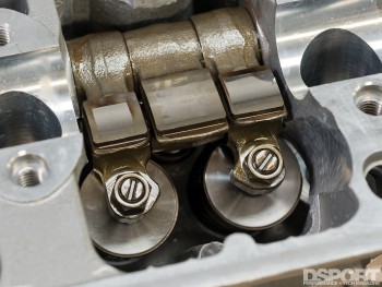
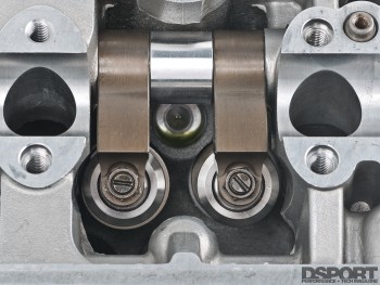
(L) Honda’s B-series VTEC design is an exceptional performer to 9,000RPM and beyond. (R) A VTEC eliminator system like this one from WEB CAM is necessary for extreme valve lifts at 10,000+ RPM. While you do lose the VTEC capability, valvetrain mass is reduced.
The Bottom Line
The right parts, precision machining and proper assembly are critical to maximum reliable performance for any engine. The performance aftermarket offers quality valves, springs, retainers and other valvetrain components that can extend the RPM range, increase power and still provide a long service life. If you are planning on pushing two, three, four or even six times the amount of original power output, addressing the valvetrain is a must.
