Last month, we promised to upgrade the fuel system, do a compression check, do a leak-down test and more to figure out why our GT-R had made a step backwards in terms of power output. We were then going to strap the car back on the dyno and give it another flogging.
Text & Photos by Michael Ferrara
Guess what? We didn’t get it all done. However, we are seeing some major improvements and some problems solved as we progress. Sharing these with you will hopefully allow you to avoid some of these problems on your own street or racecar.
The Fuel System
After speaking with Weldon Pump, we had a pretty good idea of how we would design our fuel system. We would do some things exactly by the book and we would make some compromises based on the project parameters that we set.
One project parameter that we set is that we were going to maintain the factory fuel tank and an in-tank fuel pump configuration. Our logic was that we wanted to keep fabrication to a minimal and we wanted the low noise output of an in-tank pump configuration. Of course, there was a tradeoff to this decision. We would need two in-tank pumps to meet the flow demands of an engine capable of producing over 1000 horsepower at the flywheel. Using two pumps, instead of one, complicates the plumbing situation. Two pumps also introduce a greater likelihood on engine damage when a pump failure occurs. If a single pump fails, then engine will continue to run normally until fuel demand exceeds the max output of a single pump. At that point, fuel pressure will begin to drop, fuel delivery will be less and a lean condition will result. This lean condition can then cause damage to the engine. The importance of a fuel pressure gauge in the driver’s compartment is paramount on multiple pump applications. In this way, a decrease in fuel pressure may be able to be recognized before any engine damage occurs.
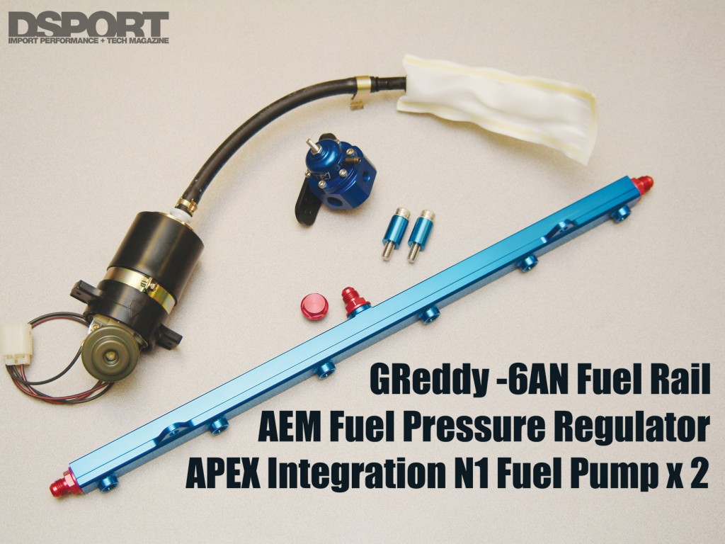
 As for the components we would use on our fuel system, a pair of Apex Integration N-1 R33 fuel pumps would establish the foundation. This pair of pumps when plumbed correctly would have enough output capacity to supply the engine with enough fuel to exceed 1000 horsepower at the wheels. As for the fuel lines, a pair of -6 lines will come from the pumps to a Y that joins the flow together into a -8 line. This -8 line would run forward to the front half of the fuel system. This front half would consist of a -8 filter assembly that would flow into another Y that would convert the -8 into two -6 lines. The two -6 lines would then feed both ends of the GReddy fuel rail. A single -6 line located in the center of the GReddy fuel rail would carry the return fuel to the AEM fuel pressure regulator that would feed back to the gas tank.
As of this article, we have completed the front end of the fuel system. At this time we have located some of the sources of our engine’s drop in performance. One problem was that the injector clips were not making good contact with the injectors themselves. This caused a misfire once the engine vibration became strong enough to shake the connection. We will be tracking down some connectors and rewiring the entire injector harness to eliminate any similar problems in the future.


