If you build enough project vehicles, there will come a time when you either have a need or a want to improve the braking system. In most cases, the parts you need to meet your goals will be available off the shelf. However, you may need a custom solution to achieve your goals. Whichever the case, a proper understanding of brake system upgrades is a must. Having this knowledge will allow you to choose the right parts the first time around. Just going bigger isn’t necessarily going better. In fact, upsetting the balance of the braking system can result in a system that offers decreased braking performance. In part one of Brake 201, we will discuss the primary function of the brake system, outline the wish list of an ideal brake system, conduct a reality check then transition to an explanation of the role for each of the components in the brake system.
By Michael Ferrara // Photos by Joe Singleton
DSPORT Issue #200
Function
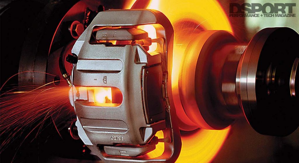
In the simplest sense, the braking system slows the wheel’s rotation to stop the vehicle. To achieve this goal, the braking system converts energy from one form to another. All of the motion energy (kinetic energy) that your car is carrying is eventually turned into thermal energy (heat) when you apply the brakes to slow or stop your vehicle.
The Ideal Brake System
Let’s talk about the ideal brake system first. What would we want it to do? Our wish list would likely include the ability to stop or slow down a vehicle in a minimum amount of distance. This system could also be used repeatedly without a performance drop. The brake pedal effort would require minimal effort with an amount of travel that allows for exceptional modulation of the brake. Pad and rotor life would be exceptional. Noise would be nonexistent. Finally, no brake dust would be released to dirty our wheels. While this list of ideals include some achievable goals, a real-life brake system must compromise some of the ideals to deliver maximum performance.
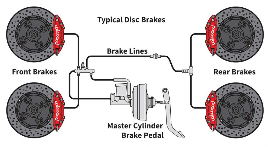
In a brake system without ABS, the layout will be similar to above. The master cylinder, booster, master cylinder and caliper piston area will all influence the travel and effort required to apply the brakes.
The Ideal Brake System
- Minimal Stopping Distance
- Maximum Endurance
- Minimal Pedal Effort
- Optimized Pedal Travel
- Superior Brake Modulation
- Extended Pad/Rotor Life
- Zero Noise
- No Brake Dust
Reality Check
There are a number of items on the Ideal Brake System list that are achievable with a properly designed braking system. A properly designed braking system can deliver minimal pedal effort, optimized pedal travel and superior brake modulation. Most modern OEM brake systems work well in these regards with few exceptions. To achieve this result, the pedal ratio, master cylinder size, booster ratio, caliper piston area and flexible line compliance must all be considered. Even the rigidity of the master cylinder and pedal mounts play a role. Many times all it takes to make an OEM brake system better in this regard is to install a set of stainless-steel braided Teflon inner brake lines and a master cylinder brace. These two items will eliminate the undesirable sponge feel of the pedal. When designing a custom system from scratch, starting point pedal ratios, master cylinder bore sizes and caliper piston areas will put you in the ballpark. An adjustment of the pedal ratio and/or master cylinder bore size will allow the system to be tuned to perfection.
Brake System Components
- Brake Pedal Assembly
- Brake Master Cylinder
- Brake Booster (Power Assist)
- Brake Fluid
- Brake Lines (Hard)
- Brake Lines (Flexible)
- Brake Bias Control
- Brake Calipers
- Brake Pad Anti-Squeal Shims
- Brake Pads
- Brake Rotors
- Brake Cooling Ducts
- ABS System


