
It’s the current that kills you. Currents above 10 milliamps can induce muscle contractions so strong that the victim cannot let go of the wire that’s shocking them. At 20 milliamps, breathing can become labored, while 75 milliamps can cause breathing to cease. At 100 milliamps, ventricular fibrillation of the heart occurs. This spastic twitching of the heart’s ventricle walls can result in death. At 200 milliamps, the human heart can forcibly clamp itself during the electrical shock. This may actually protect the heart from fibrillation and increase the victim’s chances of survival. Now don’t worry, your body’s natural electrical resistance is high enough to limit current flow from a vehicle’s 12-volt electrical system. However, understanding the importance of the current demands of different systems on a vehicle is key to designing and improving a vehicle’s electrical system.
Text by Michael Ferrara // Photos by Jun Chen
DSPORT Issue #156
High Load Reality
Motors, fans, pumps, horns and non-LED lighting have high current demands. High current demands require electrical leads and switches capable of staying cool and collected when serious amounts of current are flowing. This means larger gauge wires and heavy-duty switches. Both are heavy and expensive. A means of minimizing the length of large gauge wiring and a replacement of high-amperage switches with low-amperage switches reduces weight, cost and improves efficiency.
Voltage Drop
When smaller than optimum size wires are used, voltage can drop from the beginning to end of the circuit. While a 10-percent drop in voltage may not sound like a big loss, the brightness of a light may be reduced 33% from such a voltage drop.
 While all 12V components will deliver improved performance with a full 13.5-14.5 volts, lighting is one area significantly affected by drops in supply voltage. If your headlights are only receiving 90 percent of the system voltage (12.1 volts instead of 13.5 volts), the output will only be 67 percent of what it could be with a full 13.5 volts.
The Relay Solution
In 1835, Joseph Henry invented the DC relay. Henry showed that a smaller electromagnet could be used to switch a larger electromagnet on and off. This allowed very small currents on small wires to switch over a high-current switch. The relay was born and this technology made the telegraph and telephone possible.
Relay Position
The best location for a relay minimizes the length of wire between the source (battery or fuse box) and the device. This position not only reduces the voltage loss in the line, but also reduces the total weight and cost of the system. Since the control or trigger wires for a relay can be extremely small in size, switches can be located in the most convenient location.
Relay Mechanics
A relay is essentially a remote-controlled switch. There are essentially two systems within every relay. First, there is the control circuit. The control circuit, sometime referred to as a trigger circuit, is what “energizes” or activates the relay. This is the remote-control portion of the device. The switching portion or power circuit is the portion of the relay where the high current voltage is supplied from the line (battery) to the load (device).

4-PIN RELAY
Normally Open Relay (Form A / SPST-NO) A normally-open 4-pin relay closes its “power”circuit when current is passed through its coil. Normally-open relays are used for vehicle lighting, horns, Cooling fans, blower motors, A/C fans air-conditioning. They are the most common relays found on vehicles.
85 and 86: Trigger
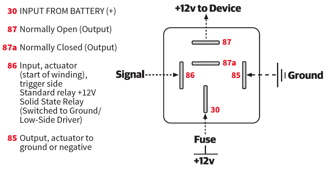
On common 4- and 5-pin relays, one pair of terminals is on opposite sides with the blades in a parallel direction to each other. When numbered, these will be terminal 85 and 86. Most relays require a positive voltage to be applied to one terminal while the other terminal is negative or ground. However, this is not the case for solid-state relays. Solid-state relays actually have a constant ground on one terminal (#85) while the other terminal (#86) is a switched to ground signal to close the power circuit in the switch. As solid-state relays will become more common in the near future, it’s a very good practice to always wire terminal 85 to ground. On non solid-state relays, terminal 86 will need to have a small current of +12 volts to activate the relay. However, this is not always the case. On solid-state relays, Terminal 86 will be a switched ground (most likely the output from a low-side driver from an ECU). Solid-state relays are unique in that both sides of the control circuit must be grounded in order for the power circuit to close and transfer power from 30 to 87.
30 and 87: Power
On common 4-pin relays, a pair (4-pin) of terminals opposite to each other with the blades perpendicular will make up the power circuit of the relay. Terminal 30, which shares the same blade orientation as terminals 85 and 86, is where the power should come into the relay. A fused power source should supply the current to terminal 30. Terminal 87 is the load size of the relay. This is where the device will draw current from once the relay is energized. Terminal 87 should go to the positive wire on the fuel pump, light, blower, fan or other electrical device needed to be switched. While a 4-pin relay will also function with the 30 and 87 leads reversed, this is a bad practice as you will run into issues on both 5-pin and solid-state relays when the proper conventions are not followed.

5-PIN RELAY
Change-Over Relay (Form C . SPDT) A change-over relay switches current from one terminal to another. Terminal 87 will still be normally open and closed only when the control circuit is energized. However, terminal 87a will be closed when the relay is not energized and open when energized.
87a: 5-Pin Changeover
While a 4-pin relay acts as a remote control switch, a 5-pin relay can be used to supply current to one source when not energized and switch the current to a different source when energized. When a 5-pin relay is not energized, Pin 87a will be connected to Pin 30. If Pin 30 has +12 volts, pin 87a will have the same. When the relay is energized, pin 87a will shut off and pin 87 will have the +12 volts. If a certain set of lights were to be on when the relay was off, but turn off and activate a second set of lights, a 5-pin relay would allow this changeover to easily occur.

4-PIN SOLID STATE RELAY
Normally Open Relay (Solid State / SPST-NO) A normally-open 4-pin relay closes its “power”circuit when both sides of the control circuit (85/86) are closed to ground. Solid State relays can be pulse width modulated. While a solid state relay can plug into a conventional relay holder, the wiring must be reassigned so that pin 85 is a constant ground and pin 86 gets grounded when the relay needs to turn on the power circuit.
The Solid-State 4-pin Relay
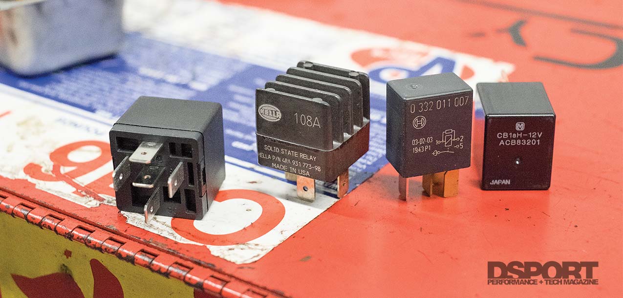
Solid-state electronics feature no moving or wearable parts. In essence, they could conceivably last forever. They make no noise when switched. The Hella 931773987 is the most popular solid-state relay in the conventional form factor. This relay requires that proper assignment be made to all four terminals. Fused power into terminal 30; power supply to device on terminal 87; terminal 85 to constant ground and terminal 86 to be the switched control to ground. Grounding terminal 86 energizes the relay and closes the 30-87 power circuit. This relay can be run from an ECU at duty cycle between 10 and 90 percent. Frequency can be from 1 to 1000Hz. This relay only takes about 0.0001 seconds to energize with a closed ground or 0.000075 seconds to release. The relay is ideally suited to be used with resistive loads when under pulse width modulated frequency control. Common examples of resistive loads include most electrical heaters, and traditional incandescent lighting loads. Hence you could use a PWM controlled solid state relay to control the temperature of an electric rear defroster, heated seat or light bulb.
Pull-Box: Why use a relay?
The wire leads that carry current, also produce resistance that results in a voltage drop. The resistance of a lead is dependent on its length and its cross-section width or gauge. Long and thin wires add the most resistance to a circuit.

Choosing the Right Relay
In addition to choosing between a 4-wire (normally open, SPST) relay and a 5-wire changeover relay, there are other considerations that must be made. Current handling capacity, package size and technology must also be considered. The most common, conventional relay used for automotive applications is the 5-pin 30A/40A relay. These relays are so common that they are made everywhere around the world. Unless you want to be replacing these on a regular basis, stick to the relays made in the USA, Japan or Germany. In practice, these relays are generally not happy with high-current cooling fans and high-current demand fuel pumps. For those applications, high-current relays (that require wider blade terminals to support larger gauge wires) are the way to go. We also really like using the solid-state relays on any circuit driven by a low-side driver from an aftermarket ECU. The lack of a positive voltage on the control circuit of the solid–state relays eliminates the voltage spikes that occur when a conventional relay is switched off. This adds an extra layer of protection to the ECU. Finally, there are also some smaller footprint “mini” relays that work great when current demands are more modest. Since solid-state, high-current and “mini” relays are a bit harder to locate while on the road, it’s always a good idea to carry a spare.
The Bottom Line
Running a 2-gauge wire from your battery to your ignition switch and back to your starter would be a reality if the relay was never invented. Fortunately, the relay is alive and well. Understanding the history, science, best practices and applications of relays will allow you to design, service and improve your vehicle’s electrical system for maximum performance and efficiency.
