
Drive-by-wire (DBW) throttle is a technology that is hated by some and praised by others. Purists often claim that DBW throttle bodies disconnect the driver from the engine. They argue that throttle response is slower than a cable throttle and that the OEM uses DBW throttle bodies to limit the fun. While OEMs are always using control systems to limit the fun (usually to improve the safety of a vehicle), the actual measured lag between flooring that DBW pedal and getting full throttle at the DBW throttle body is usually somewhere between 30 and 80 milliseconds. While there are a few undeniable disadvantages to a DBW throttle system, the love for mechanical throttle systems may simply be some sort of euphoric distortion sensed by our bodies. After all, the actual throttle lag is just a fraction of the time it takes a human to blink (100ms). On the contrary, the potential advantages of DBW throttle systems are significant. These advantages can lead to increased performance, improved engine reliability and enhanced drivability.
Text by Michael Ferrara
DSPORT Issue #234
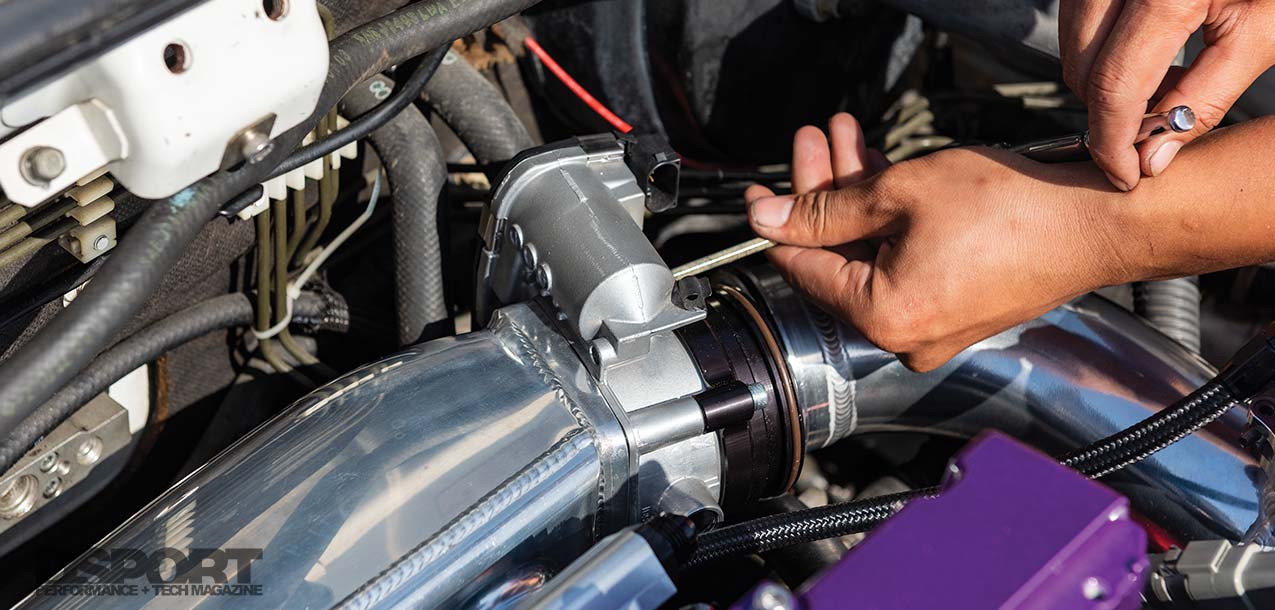
 While nearly all modern vehicles have a drive-by-wire (DBW) throttle system, converting earlier mechanical systems to DBW is gaining in popularity. Most enthusiasts choose a Bosch electronic throttle like the picture above. These are available with 60mm, 68mm, 74mm and 82mm throttle plates to satisfy a wide range of applications.
Not a Fan at First
 I was not an immediate fan of DBW throttle despite having an unintended acceleration issue on a mechanical throttle vehicle that could have killed me. My 1969 Camaro used a mechanical linkage throttle system (worse than a cable). When the left side motor mount failed over time, the engine was able to twist enough itself to pull on the throttle assembly opening the throttle even more. I was at a stop light and gave the car a regular amount of throttle input. The next thing I know the pedal pulls itself to the floor and the engine is at full throttle. Fortunately, I was the first car at the stoplight and I had enough time to push the transmission selector into neutral which eliminated the torque on the engine that caused it to rotate and pull up on the throttle. A cop witnessed what looked like an exhibition of speed away from the stoplight and quickly pulled me over. I was able to figure out that the motor mount broke and had the car towed home for repair. While some may think I would be a fan of DBW throttle due to the fact it eliminates this possibility, I definitely wasn’t sold when the first-generation systems rolled out.
First-Gen DBW
One reason for a dislike by some for DBW throttle systems was the lack of performance from many of the first-generation OEM DBW throttle systems. While one might think that there are several performance enthusiasts among the many OEM automotive engineers in the world, the reality is that there are very few that are passionate about what we call performance. Instead, OEM engineers tend to focus on how a commuter uses a vehicle rather than how a DSPORT reader pushes a car to the limits. For example, many first-generation DBW systems lacked a launch mode. In fact, some had throttle limits set in such a way that you couldn’t even rev the engine to a decent launch RPM if the ECU detected that the vehicle was stopped. To meet minimum fuel mileage requirements, early DBW vehicles often had the pedal to throttle relationship programmed where the accelrator pedal didn’t appear to do much of anything until nearly floored.

Unlike a mechanical throttle system, the “feel” of a DBW throttle system can be significantly changed by the tuning of the pedal input to throttle position maps. Early R35 GT-Rs had horrible throttle lag which was improved slightly between 2009 and 2011. By 2012, Nissan completely eliminated the perceivable throttle lag on the 2012 GT-Rs.
The reality is that a DBW throttle provides the opportunity to establish any number of relationships between what is happening at the accelerator pedal and what is happening at the throttle body. Personally, I remember how bad this relationship could be when driving the first R35 GT-Rs delivered to the States. You would mash the accelerator pedal only to wait what seemed like seconds before the throttle body would react. It was like one of those earlier versions of Windows that asked you 10 times if you were sure you wanted to do what you typed. “Are you sure you want full throttle (Y/N)?” Press “Y” again to get full throttle. Year after year, Nissan improved it to making it a non-issue by the time the 2012 R35 GT-R (DBA) was released.

For peak performance of the DBW throttle system, the tuner must optimize the pedal to throttle relationship.
System Overview
Modern DBW systems consist of an electronic pedal assembly that has redundant pedal position sensors. The pedal assembly receives power and ground from two separate circuits (in case one of these circuit fails). The pedal assembly features two position sensors that send the pedal position information to the ECU. These two sensors output position signals that will be the same as long as both of the position sensors are functioning properly. If the power or ground circuit is interrupted to one of the sensors, the signal output from the two position sensors will not match. If one of the sensors fail, the position signals will not match. By employing this strategy, the pedal assembly can let the ECU know if it is functioning properly. If the two-sensor strategy was not used, the ECU could receive a signal that the pedal was being floored or that it was not being touched if a sensor failed or the power or ground was interrupted to a single position sensor.

While a cable-drive mechanical throttle provides a barely measurable advantage in throttle response compared to a properly tuned DBW throttle, it simply cannot provide the features offered by a DBW throttle system.
Like the pedal assembly, the electronic motorized throttle body of the DBW system also features redundant throttle position signals. Most DBW throttle bodies have 6 wires. Two wires are used to control the positioning motor that opens or closes the throttle. Another two wires are used to supply the +5v power and ground circuit for the throttle body’s two internal TPS sensors. The final two wires are the signal outputs that report the throttle position to the ECU. Like in the case of the pedal assembly, if these two signals do not match, then the ECU knows that something is wrong and it can put the engine into a safe or limp mode until the problem is corrected.
In between the electronic accelerator pedal assembly and the electronic throttle body you will find the ECU in the DBW throttle system. It is how the ECU controls the throttle based on the pedal position information and the other inputs into the ECU that dictates whether the DBW system is accomplishing good or bad. While there are some hardware and processor speed parameters that can influence the performance of the DBW system, the firmware and tuning of the DBW tables will generally carry more weight in the end results. With some aftermarket ECUs allowing for custom firmware to be written, the possibilities for using DBW throttle systems for good (or evil) are simply a matter of the level of creativity and intelligence of the tuner.

The electronic pedal circuit is made up of two redundant pedal position sensors. The redundancy in sensors provides safety by ensuring that the actual pedal position is known by the ECU.
The Bottom Line
Because fans of high-fidelity audio are looking for a faithful reproduction of the recorded source material, laboratory testing and development of audio components often tests an audio component’s ability to take a signal and amplify it without adding anything that wasn’t there to begin with. With a theoretically perfect amplifier, the signal going in and the signal coming out are identical with the sole exception being the magnitude of the signal. Hence there is zero distortion. While this may be pleasing to the audio engineer in the lab, it may not “sound” the best to the listener. The reason is that some distortion or change to the output signal can sound better. Euphonic distortion is a term normally used to describe the warm tones that tube amplifiers add while amplifying the source signal. While a cable-based mechanical throttle system may emulate a system where the input and output signals are identical and in sync, it may not “feel” the best. On the contrary, a properly-tuned DBW throttle system can add some “euphoric”distortion to “feel” better while also delivering improved performance, reliability and safety.

Benefits of Drive by Wire (DBW) Throttle
- No throttle cable issues: While a throttle cable represents a remarkably simple solution, it does have its drawbacks. Over time the steel cable can stretch, and it may require adjustments to allow proper idle and full-throttle operation. DBW systems do not suffer from this. When engine swaps or intake manifold upgrades are made, the OEM throttle cable may be too long or too short to function properly. With a DBW system, none of this will be an issue.
- Eliminates the need for Idle Air Control Valve: The idle air control valve is an ugly and necessary component on conventional mechanical throttle body engines. This valve allows additional air to be drawn into the engine to increase the idle during the after-start and warm up periods for the engine. This component is eliminated with a DBW throttle. While the idle control is normally accomplished with the idle air control valve, the ECU simply adjusts the throttle blade in the electronic throttle body to reach the target idle.
- Adds Redundant TPS sensor: With VE-based fuel strategies, many tuners prefer to use TPS vs. engine speed mapping for the VE tables. When a TPS sensor is acting up, sometimes hours are wasted troubleshooting the issue. Thanks to a DBW system’s dual TPS sensors, a faulty sensor is quickly identified by the ECU.
- Improved Driveability of Big Throttle Bodies: When engines go to larger throttle bodies, the driveability can suffer. Whereas it may have taken a throttle opening of 20 percent to allow enough airflow for 200 horsepower on the stock throttle body, it may only take five or 10 percent of throttle opening on a larger throttle body to support 200 horsepower. As a result, the pedal travel between idle and 200 horsepower may be only a half or a quarter of its original travel in this instance. Essentially, the throttle control becomes less precise on conventional throttle bodies when the throttle body diameter increases. On a DBW system, the ECU can map the relationship between pedal position and throttle opening. As a result, the DBW system can be calibrated to deliver a percentage of total torque available based on throttle position instead of simply matching the percentage of pedal position travel to percentage of throttle position opening.
- Easier Part-Throttle ECU Calibration: As mentioned before, many tuners prefer to calibrate the fuel tables based on throttle position versus engine speed. On a mechanical throttle system, holding the engine at a specific throttle position is a challenge. Mechanical throttle stops need to be put in place and the entire process can be a real headache. On a DBW system, getting the engine to hold at a specific throttle angle is a cinch. You can simply build a temporary table for the pedal input to throttle angle to stay at a set throttle angle, let’s say 10 percent for this example, any time the accelerator pedal is between 10 and 90 percent.
- The Launch Mode w/Throttle Control: Some ECUs allow for the engine and vehicle to be placed in a “launch mode.” While in this launch mode, a preset boost target and engine speed target is usually specified. When the ECU has no control over the throttle, ignition retard, selective cylinder ignition cuts, and wastegate solenoid manipulation are used to try to get the engine ready to launch at the desired boost and engine speed. Unfortunately, the ignition limiters used can often put the engine in a state where it can damage itself when on these limiters for too long. When a launch mode can also incorporate control of the throttle, a launch mode that is easier on the engine can be used since engine speed can also be manipulated in part by throttle position.
- Torque-Based Requests and Deliveries: Some ECUs can calculate a remarkably close approximation of the torque output of the engine based on knowing the engine’s displacement, its volumetric efficiency, its pressure ratio (manifold to atmospheric pressure ratio), air density, throttle position and fuel flow. Since the ECU can accurately estimate the torque output, the ability to map an engine based on torque requests (based on pedal position and tables) is possible. If estimated torque delivery is below the requested, the ECU can open the throttle more. If the estimated torque delivery is more than the requested amount, the throttle can be closed more. Since torque output is directly proportional to cylinder pressures, doing engine calibrations with torque-based limits in place can keep the engine (or driveline for that matter) from exceeding desired torque output levels.
- REV-MATCHED Downshifts and No-lift upshifts: When an ECU has control over an electronic throttle body, it may also have the ability to perform rev-matched down shifts like some OEM vehicles offer. The ECU will also need to know the state of the clutch (engaged or disengaged), too, so that it knows when an upshift or downshift is occurring. On some engine and transmission combinations, there may be merits in optimizing the throttle for upshifts too.
- Traction Control via Throttle: Since a DBW system puts the electronic throttle body under the control of the ECU, it is possible to have the ECU use a traction control strategy. On 2WD vehicles, the ECU will have to measure at least one of the driven and one of the non-driven wheels to calculate the slip percentage. On AWD vehicles, traction control requires a GPS signal to calculate actual vehicle speeds as all four tires can be spinning while there is a loss of traction.
- Cruise Control and Valet: DBW systems do not require any additional motors, linkage or cables to execute cruise control. Some ECUs will not only be able to do cruise control, but they can offer valet modes. With a valet mode, you can set limits to the maximum throttle allowed while in the mode. It’s a great consideration if you aren’t always the one loading or unloading your race car between events.

This diagram shows the overview of signal, power, ground and logic circuits on a typical DBW throttle system. The electronic pedal reports pedal position to the ECU while the throttle body communicates its throttle position to the ECU. The ECU supplies the power and ground circuits for all the position sensors and also provides the power to drive the positioning stepper motor in the throttle body. The programming in the ECU determines the relationship of pedal to throttle while constantly ensuring that all position signals are valid.
Drawbacks of Drive-by-Wire
- Throttle Lag: ECU must process and compare the two pedal position (PPS) signals sent and ensure that both channels are sending the same value (within the set tolerance of each other). At the same time the ECU is comparing the two throttle position sensor (TPS) signals coming from the throttle body to ensure that both of those channels are sending like TPS signals. The ECU then references the calibration table that tells it what the desired throttle position should be for the pedal position being input. If the desired throttle position is determined to be higher than the reported TPS value, the ECU sends a signal to the throttle body motor to open the throttle. If the desired throttle position is lower than the reported TPS, the ECU sends a signal to the throttle body motor to close. The time for this to all happen varies based on the processing speed of the ECU and the speed of the electric motor. Typically, most DBW systems show a delay around 50ms. For comparison, the average human blink takes 100ms. While there is a measurable lag with a DBW system, it only amounts to half the time it takes to blink.
- Uses More Analog Inputs on ECU: The ECU will need to use three additional analog inputs (four total) versus a conventional mechanical throttle body that uses only one analog input to the ECU. Essentially there are two redundant pedal position sensor (PPS) inputs into the ECU along with two redundant throttle position sensor (TPS) inputs into the ECU. Why is this a drawback? Because these additional analog channels used less are available for other sensors. Fortunately, many sensors can now operate on the CAN network of modern ECUs so EGT, A/F-Lamba and even additional analog channels can be communicated to the ECU via CAN.
- Requires DBW Compatible ECU: Some ECUs do not have the DBW motor driver required, others may only have one motor driver. One motor driver per electric motor driven throttle body is required. If you are running dual DBW throttle bodies on an engine, you need to make sure the ECU has two DBW throttle driver circuits.
- Conversions Require Pedal Replacement: while the process is not extremely difficult, very few have the experience of replacing an original mechanical accelerator pedal assembly with an electronic accelerator pedal assembly. When mounting the electronic accelerator pedal, do not skimp or rush on the brackets. Proper support of this pedal assembly is a must. Make sure there is no interference with the carpet, floor mat or any other obstructions. Always finish the pedal assembly mounting first before running the wires for the harness. In this way, the wires can be made the proper length without putting strain on the wiring harness or pedal assembly. In some cases, there may be a kit available for the electronic pedal conversion. In other cases, you may look to a newer model vehicle of the one being converted for the electronic pedal assembly as these often have similar profile and are easier to fit. If not available, a Bosch universal is a good starting point.
- Redundant Circuits Must be Precisely Wired: The electronic pedal assembly and the electronic DBW throttle body must be wired correctly or a short across the circuits or a failure of a PPS or TPS can result in instant wide-open-throttle or instant closed throttle operation. These conditions can put the life of you and your engine in danger. Under no circumstance should any of the redundant signal wires be joined, spliced or connected together. It is also important to take the sensor ground and +5V sensor supply voltage from different channels on the ECU. At the electronic DBW throttle body, never join, splice or connect together the redundant TPS signal output channels. The redundancy with the position sensors in the DBW throttle system is a necessity for the safety of the engine and the driver.
