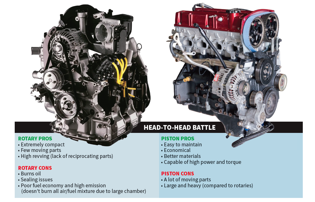
The Wankel Rotary engine: Mazda’s most prized offering is also the source of hundreds of hilarious internet memes. During a time where internal combustion piston engines were the primary technology used in vehicles, Mazda decided to develop a competing technology. In the early ‘70s, the Rotary engine powered nearly every vehicle in the Mazda lineup. When the gas crunch hit, it was still used in Mazda’s high performance vehicles. The Mazda Rotary provided benefits over piston engines, but it also came with a hefty list of shortcomings. Let’s take a look at what makes it different from a piston engine and some of its pros and cons.
Text by Bassem Girgis and Jim Mederer // Photos by Staff and Racing Beat
DSPORT Issue #206
Piston Engine
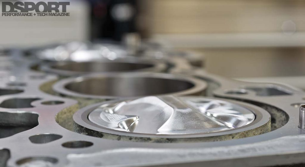
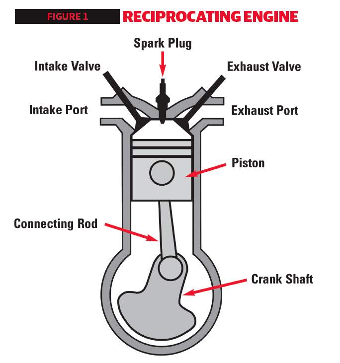
An internal combustion piston engine consists of a block, crank, rods, pistons, heads, valves, camshafts, intake system, exhaust system, and ignition system. They all work together to convert chemical energy into mechanical energy that allows your car to move. Inside the block, a crankshaft is connected to a number of connecting rods (depending on how many cylinders your engine has), and the rods are attached to the same number of pistons. As the pistons move up and down, they rotate the crankshaft using the connecting rods.
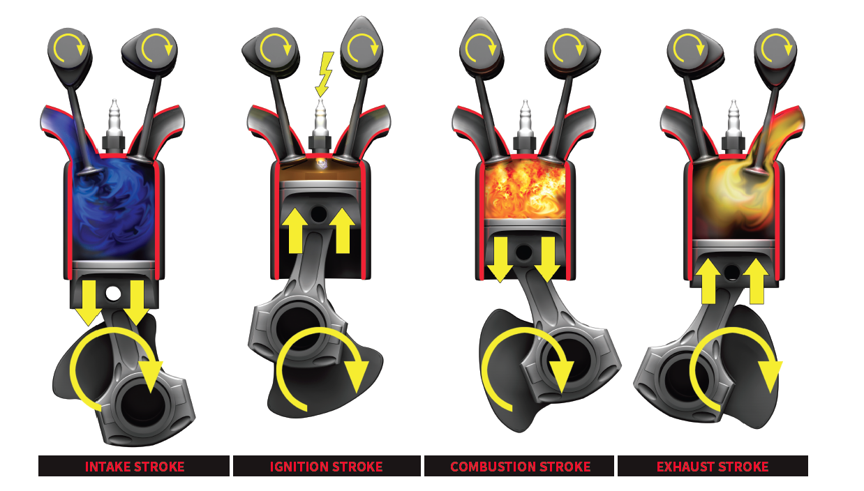
Starting with the piston at top dead center (the first step in the four-stroke cycle), the intake valves open while the exhaust valves are closed (opening and closing is controlled by the camshaft, which is synchronized to the crankshaft using a belt or chain). As the crankshaft continues to rotate, it pulls the piston down sucking air into the cylinders. By the time the piston reaches the bottom, the cylinder is now filled with air and fuel.
To complete a full four-stroke process, the piston has to make two complete passes in the cylinder.
The piston then starts moving upwards during the compression stroke. During this stroke, the intake and exhaust valves are closed. The upward movement of the piston compresses the air and fuel mixture, which mixes the air and fuel molecules as they’re pushed closer together. This process creates a mixture optimized for combustion. Once the piston is near top dead center again, the spark plug fires to trigger the combustion in the cylinder.
The power stroke creates a controlled combustion triggered by the spark. The combustion pushes the piston down the cylinder. The pressure generated by the combustion is the driving power that propels the wheels on your car. As the piston makes its way toward bottom dead center, the exhaust camshaft lobe starts to open the exhaust valve preparing for the final stroke in a four-stroke cycle.
As the cylinder starts going up again, the exhaust valves open all the way. This allows the exhaust gases to escape from the cylinders to make way for the next four-stroke cycle once again. The exhaust gases exit through the exhaust manifold, through the catalytic converter, and out through the exhaust pipe and muffler. By the time the piston is back at top dead center, the exhaust valve is almost closed and the intake valve is starting to open. Then the process repeats.
Rotary Engine
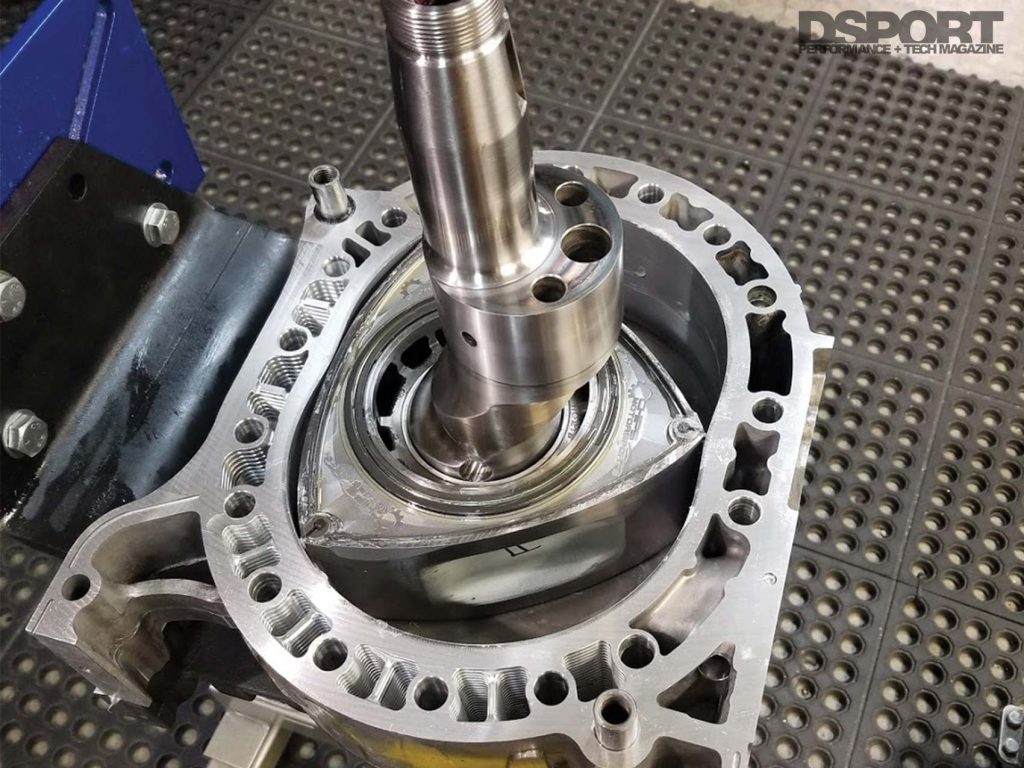
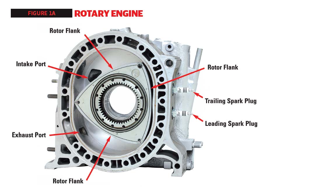
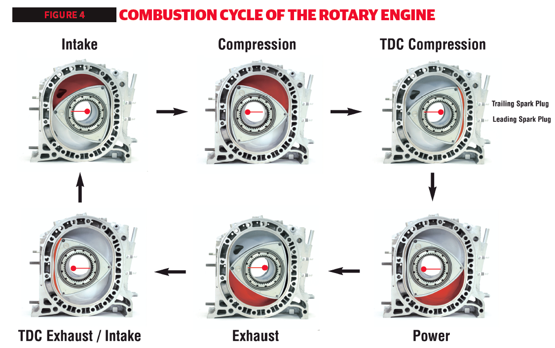
The Rotary engine features the same four-stroke cycle as a piston engine to generate power at the flywheel. Unlike a piston engine that has combustion occurring in a cylinder, the rotary engine relies upon the pressure contained in a chamber in the housing, which is sealed by one side of the rotor. The two rotors are used in place of the pistons. The rotor is three-sided, which rotates around the rotor housing using an eccentric shaft. The three sides are curved into three lobes, and the rotor housing is shaped like a rough figure eight (8). As the rotor spins inside the housing, the gap between the rotor and the housing alternates between large and small.
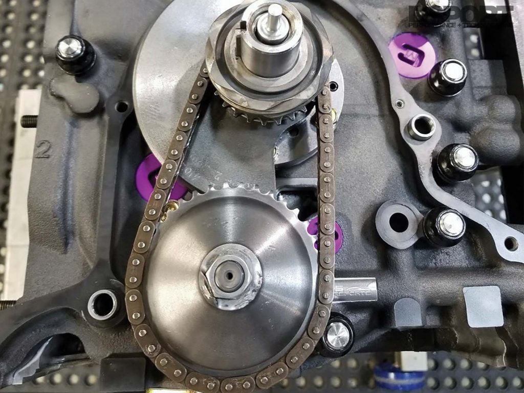
While a piston engine uses a timing belt or chain for the camshafts and valves, the only chain that the rotary engine uses is for the oil pump.
The air and fuel are ingested into the rotor housing as the volume between one of the rotor’s lobes and the wall of the housing is increasing. As the rotor spins and the volume increases, vacuum is created, which pulls air and fuel into the housing. As soon as the tip of one of the sides of the rotor clears this intake area, the next side of the rotor is starting its intake process. The rotor continues to rotate until the volume between the rotor’s lobe and the housing’s wall starts decreasing. This compresses the air and fuel mixture, similar to how a piston engine does as the piston goes upwards. The compressed mixture then goes to the next part of the housing where the spark plug is located. The spark plug fires to ignite the compressed mixture. While the bottom spark plug ignites most of the mixture through a larger opening, the top spark plug ignites fuel in the smaller end of the combustion pocket. The ignited air and fuel combusts (burns at a controlled rate), which drives the rotor around in a clockwise rotation. As the rotor continues to spin after the first bang, the volume increases between the rotor and the housing, which allows the gases to expand. The final step is when the volume decreases one last time to force the exhaust gases out through the exhaust ports before making another round and starting the four-stroke cycle once more.
Similarities: Rotary vs Piston
Combustion is what powers most engines. Both rotary and piston engines are powered by a four-stroke cycle. The four-stroke refers to the intake stroke, the compression stroke, the power stroke, and the exhaust stroke. Both engines need air, fuel, and spark to operate.
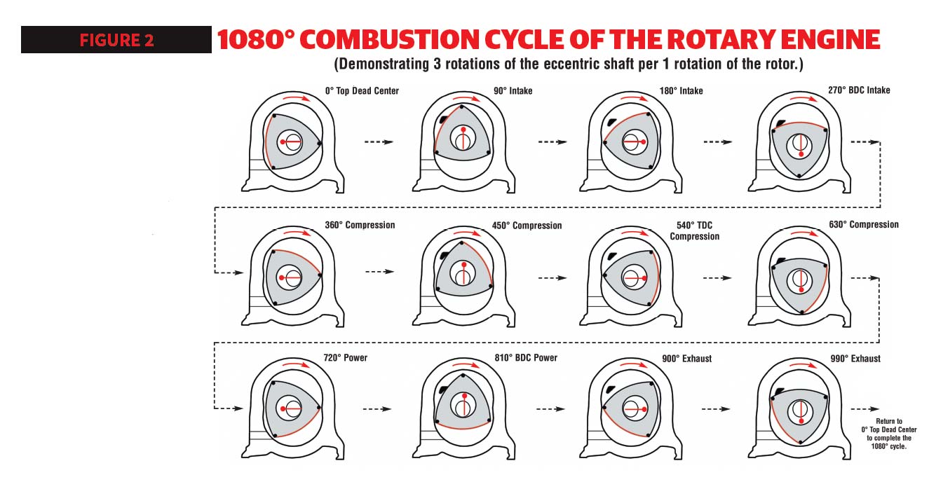
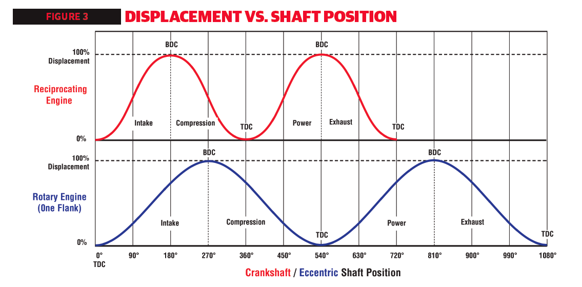
All rotational angles are quoted for the output shaft (eccentric shaft/crankshaft), not the rotor. Both engines burn a compressed fuel/air mixture to develop rotational power. Both are four-stroke engines.
The rotor spins around an eccentric shaft inside a housing. The air is compressed along with the fuel, then spark is introduced, and finally exhaust escapes through the exhaust port.
However, one big difference between them is that the recip has 180 degrees per stroke (or 4 x 180 = 720 degrees per thermodynamic cycle, this is two crank rotations for one complete four-stroke cycle in a cylinder) while the rotary has 270 degrees per “stroke” (or 4 x 270 = 1080 degrees per thermodynamic cycle, this is three crank rotations for one complete rotation of the rotor). Yeah, you may have to think about that one for a bit, but trust us, it’s true.
For each complete rotor, two times as many power pulses as a one cylinder recip is produced. This means that the 1.3L produces 1.5-times the power and torque output of a similar displacement engine.
This has some good and some bad consequences. Assuming that both engines have similar maximum RPMs, it means that the rotary has 1.5 times as many milliseconds to accomplish each “stroke.” This is one reason why rotaries breathe so well – they have more time (in milliseconds) to draw in and spit out the mixture.
They also have more time for the power stroke – a real plus to get the most out of the combustion gas, especially at high RPM. Now the bad part. The rotary also has 1.5 times as many milliseconds to transfer heat from the burning mixture into the oil and water.
This is one reason why rotaries waste more heat in the process of staying cool. Another consequence is that if you only consider one flank of one rotor, the rotary only gets 2/3 as many power pulses as the recip. However, there are actually three flanks to each rotor, each at a different point in the thermodynamic cycle, so each complete rotor actually gives two times as many power pulses (3 times 2/3) as a one-cylinder recip. Confused? Take a moment to study Figures 2 and 3 and soak it all in. The bottom line is that a 1.3-liter rotary engine delivers 1.5-times the power and torque output of a like-sized engine. It’s like a 2.0-liter piston engine.
Put another way, a 2-rotor rotary has the same number of firing pulses as a 4-cylinder recip, but because the duration of each firing pulse is 270 degrees, the engine runs smoother due to the overlap of the firing pulses.
So, what is the point of all this math? Well, the point is to get a better understanding of WHY certain things are so important to a rotary – especially heat transfer. Remember, heat is potential power, so keeping heat in the combustion mixture makes more horsepower you can use.
On to the next item: In comparison to a recip, the intake charge (once it is inside the engine) actually travels a long, tortured path. The figures above show it in detail.
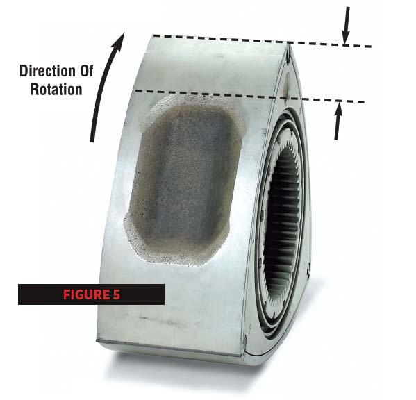
In a recip, the center of gravity of the intake charge only moves an inch or two as the piston moves back and forth between top dead center (TDC) and bottom dead center (BDC). In Mazda’s rotary, the charge moves a long way— more like 20 inches—from intake to exhaust. One bad result is that there are a lot of square inches of surface through which to transfer heat, reducing thermal efficiency. However, here is the big point: The entire mass of the intake charge must pass through the narrow area between the rotor housing and the rotor as each rotor flank passes through TDC. This is made possible by the “rotor depression” which is cast into each flank of the rotor—if it weren’t for that path, the partially burned mixture would never be able to squeeze through the narrow clearance between the rotor housing and rotor (usually around .010~.015 inch) at high RPM. There is a crude parallel with a recip that has a “pop-up” piston that tends to cut the combustion chamber in two at TDC. Some recips even cut a “fireslot” (notch) in the middle of the pop-up area to prevent it from stopping flame front propagation in the chamber. For this reason and others, the shape of the rotor depression is quite important. It also has a major influence on determining the compression ratio of the engine and, as all the “Internal Combustion Engine” textbooks point out, the compression ratio is a major determinant of the power and efficiency of any engine. Actually, this points out a weak point in the rotary—the maximum PRACTICAL compression ratio is not determined by detonation (as is common in recips) but by the ability of the burning charge to pass through the rotor depression. If the depression is too small, pressure builds up in the vicinity of the trailing spark plug causing NEGATIVE WORK! This can reduce power, overheat the trailing spark plug, and substantially increase the heat dumped into the oil and water. Therefore, the shape of the rotor depression is a cut-and-try balancing act to find the best compromise. Before we leave the subject of the rotor depression, one more point – The physical shape of the depression at its leading edge has a lot to do with the maximum usable leading ignition advance. You can understand this better if you set a late-model rotary at 35 degrees BTC, take out the #1 leading spark plug, and look into the spark plug hole. What you will see is the curved flank of the rotor rather tight against the bottom of the spark plug hole. If the spark plug were to ignite at this point, the engine might misfire because the flame front might be snuffed out (quenched) when it hit the rotor surface.
If you now turn the engine to 20 degrees BTC, the way is open to burn into the mixture in the rotor depression.
This is an important part of the reason why nearly all 1974 and later engines can run no more than 20 to 25 degrees ignition advance at high power (earlier USA model engines had a very long, shallow depression that allowed more advance). As I explained earlier, there are some parallels between rotaries and recips here – combustion chamber and piston top design are major concerns in recips – but there are some distinctive items to consider when working with rotaries.
Now What?
The truth is, there isn’t a lot that you can do to change the shape of the combustion depression, especially in 1989 and later engines with thin casting walls, but you can do some useful things. For one thing, you can ensure that the distance from the apex seal groove to the leading edge of the combustion depression is the same distance on all flanks of all rotors so that all will tolerate the same ignition timing (grind the leading edge of the depression as necessary).
Next, you can try to reduce heat transfer into the rotor by polishing the combustion depression and/or coating it with a “heat barrier” coating (Note: Do not add any measurable thickness to the curved flank of the rotor, otherwise the rotor may hit the rotor housing). Many recip racers do the same sort of things to pistons and combustion chambers for the same reasons. I know it isn’t easy for those of you who are not deeply familiar with rotary engines to wade through this information, but if you don’t understand these basic concepts, other matters (like port timing and ignition timing) will make no sense later on.
I’ll give you one more item to think about – the spark plug. Books have been written about rotary engine ignition, so I’ll only touch on one area – the heat range. For those who don’t know it, rotaries tend to use very cold spark plugs – that is, plugs that cool their electrodes well through the water jacket. There are many reasons for this, but one of the most obvious is that, while the reciprocating engine has burning mixture around its spark plug for a nominal 180 degrees (the power stroke) out of 720 total degrees (or 25% of the thermodynamic cycle time), the rotary has burning mixture around its leading spark plug for roughly 70% of the cycle time.
Jim Mederer (1942-2016) shared his knowledge of rotary engines with us in the second issue of Drag Sport in 2002 before we became DSPORT Magazine. His legacy will live on as a pioneer of all things rotary. Despite not being with us anymore, he will always be remembered for paving the way in the development of rotary engines in the performance world since the ‘70s.
Since it gets so little “cool-off” time, it must be cooled through the water jacket. This is not really the case with the trailing spark plug – it only has burning mixture nearby for 25%~30% of the cycle time, similar to a reciprocating engine. Other circumstances cause it to get a lot of heat input – but we’ll save that for another time.


