Attention to detail is often the difference between winning and losing. Fuel Tech 101 explored the basic components that make up the fuel system: fuel tank, fuel filter(s), fuel lines, fuel rail, fuel pressure regulator and fuel injectors. Fuel Tech 101 also detailed the math behind choosing pumps and injectors that meet the maximum fuel demands of the engine. In Fuel Tech 201, we’ll build upon these basics to explore detailed products, techniques and strategies that compose a high- performance fuel system.
Text by Michael Ferrara
DSPORT Issue #158
Understanding Ideal
Ideal leads to perfection. In order to engineer and design the perfect fuel system for any application, it’s important to understand the ideal level of performance expected from each component in the system. In some cases, the ideal exists. In others, technology continues to push to reach the ideal.
Getting Tanked
Starting from the tank, an ideal fuel system would have a fuel storage device (tank, cell or bladder) with adequate capacity, superior fuel “slosh” control and an easy-to-access fill neck. Surprisingly, factory fuel tanks are ideal in many respects. Factory fuel tanks offer the advantage of conforming to the vehicle’s nooks and crannies for maximized capacity. Factory tanks are also engineered with an easy-to-access filler. A factory tank usually just falls short in the fuel slosh control criteria.
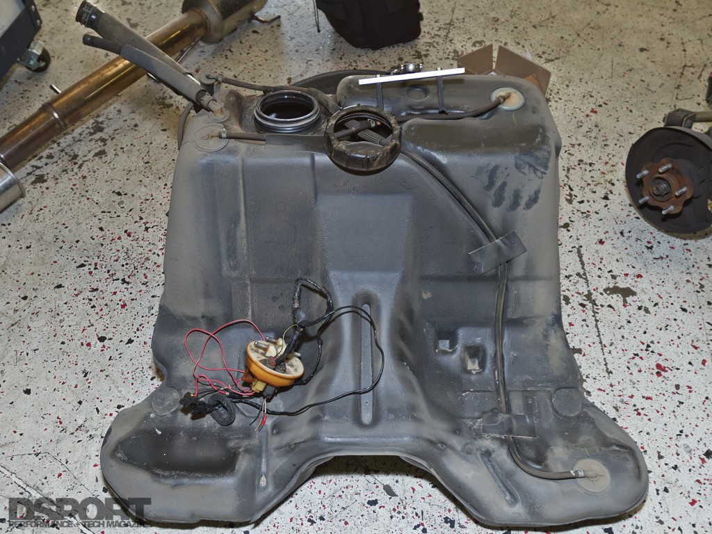
This factory fuel tank (manufactured from plastic) makes use of every bit of available space under the chassis. Fuel cells aren’t as space efficient.
While a fuel cell usually incorporates foam to properly address any fuel slosh issue, it requires the vehicle to be modified to fit the fuel cell. Hence it doesn’t do well to maximize capacity for the amount of space it takes compared to the factory tank. In addition, most fuel cell installations lack an easy-to-access filler.
A vehicle-specific fuel bladder offers the advantages of the factory fuel tank while providing good slosh control. They might be considered an ideal solution until you consider that they only have a 5-year lifespan (dictated by the racing sanctioning bodies that allow their use). Most fuel bladders are made from rubber-based materials that aren’t compatible with fuels containing more than 15 percent methanol or ethanol. Significantly more expensive Fluromer-based materials must be used for bladders that are “Flex-fuel” approved.
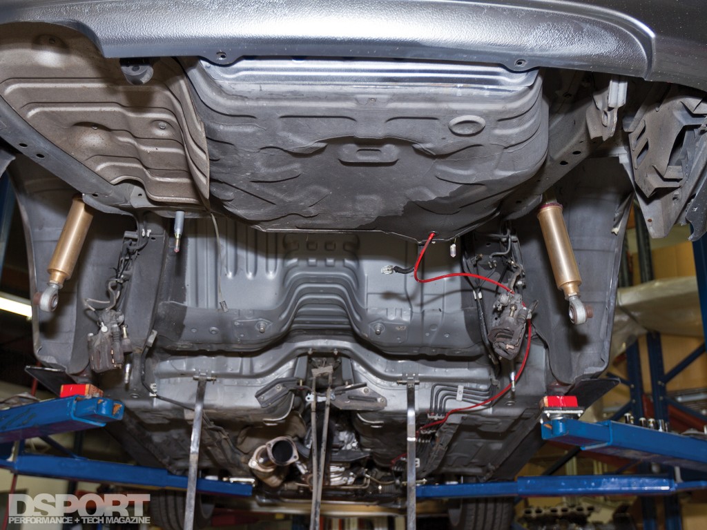
Without the factory tank in place, the underside of the chassis is cavernous. But to fabricate a direct replacement with the same fuel capacity would be costly and laborious.
Tank Tuning
A factory tank doesn’t do well at slosh control, a fuel cell wastes space and is difficult to fill and a fuel bladder has a limited lifespan. How can these be made more ideal? When external fuel pumps are used, modifying a factory tank to incorporate a sump can reduce the negative effects of fuel slosh. When in-tank pumps are used, some manufacturers offer solutions that require cutting a hole in the fuel tank to accommodate a drop-in pump and baffled pickup arrangement. Of course, many people aren’t comfortable cutting into a fuel tank. Fortunately, there is a new technology on the market that has extreme promise in simply transforming a factory tank into an ideal performer. Holley Performance recently released its new HydraMat series of products. This patent-pending solution uses a special mat material that wicks the fuel up from all corners of the tank and ensures that the pump always has fuel at its inlet. The HydraMat also works as a screen or prefilter for the pump removing larger particulars that could reduce pump life. The smallest HydraMats measure 8” x 3” and retail under $140, while larger mats can be up to 30” x 14” in size with a price tag just under $700. In steel tanks, the mat can be secured to the floor of the fuel tank with magnets. On composite tanks, a special bonding compound can “glue” the mat in place. The size of the mat used along with the geometry of the factory tank will ultimately determine the final results. However, based on what we’ve seen in the product demonstrations, we’d highly recommend giving HydraMat a try.
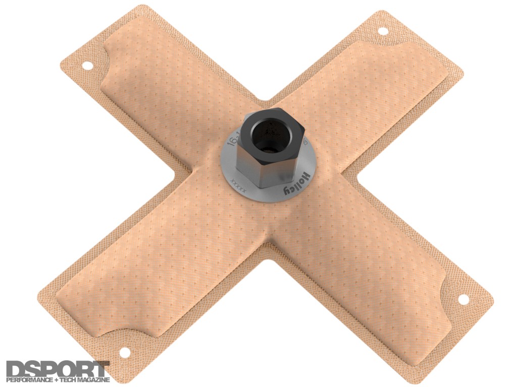
Holley’s new HydraMat technology captures every drop of fuel and defends against fuel starvation at the pump whenever fuel slosh is a concern.
One and Done
Once a fuel system has a proper tank supplying constant fuel to the inlet of the fuel pump, the next consideration is the pump itself. Ideally, a performance fuel system would only rely on one in-tank pump. Why? Single-pump solutions provide a failure mode that is less likely to damage the engine. When the pump in a single-pump system fails, the results are obvious. The engine simply stops running or fails to start. In a multi-pump system, a pump failure would result in a reduction in fuel supply capacity that may be hard to detect until it’s too late and engine damage has occurred. Fortunately, the latest-generation of engine management systems have safeguards for situations where fuel pressure and A/F ratios get in the danger zone. This has made running multi-pump systems arguably as safe as a single pump. Even so, a single pump still benefits from other advantages. Besides costing less, a single pump also has lower electrical demands. It will draw less current and power from the vehicle’s electrical system. Today, brushless fuel pump technology offers a single in-tank pump that can support extreme power levels with electrical power consumption levels at half or less than that of a conventional pump delivering only half the flow of fuel.
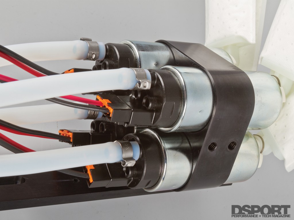
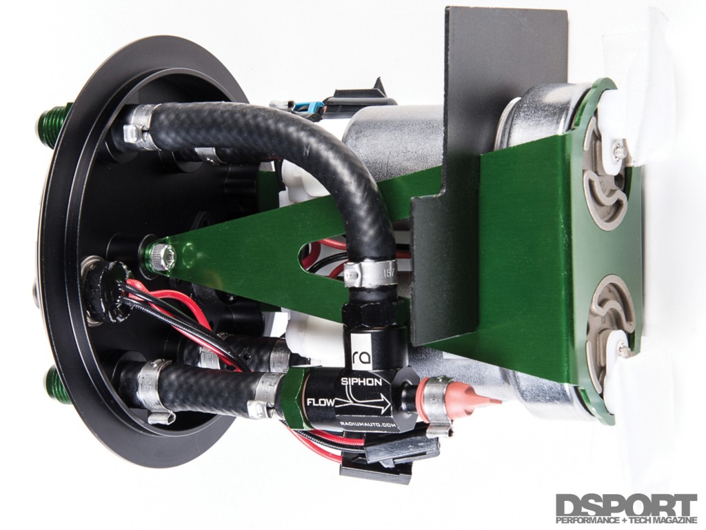
Multi-pump solutions like this Powerhouse Racing quad pump solution (above) for the Supra and Radium’s dual pump surge tank (below) offer a high fuel flow solution to big horsepower builds.
Double Down
Twin in-tank pump systems provide the same quiet solution as a single pump with increased flow and current demands. When there isn’t a single pump available to meet the fuel supply demands, a set of two, three or even four pumps working in parallel can deliver the goods. While fitting a second pump in most factory tanks is doable, adding a third or fourth can be next to impossible. Fortunately, the aftermarket offers many drop- in solutions that can eliminate the headaches.
The Urge to Surge
Lift, pump and repeat. Fuel systems that incorporate an external surge tank have been popular in many forms of road racing for years. Today, a number of companies offer pre-fabricated billet-aluminum surge tanks that allow for “in-tank” style pumps to be used. This simplifies the plumbing while eliminating the use of noisy external pumps.
As a result, these systems are becoming more popular on max-effort streetcars. Most of these systems use one “lift” pump in the factory fuel tank to supply fuel to the surge tank. The lift pump usually operates with no head pressure so it’s able to keep the surge tank full at most times. In the event that the lift pump’s inlet becomes uncovered due to fuel slosh, there is still enough reserve capacity in the surge tank to ensure that the main pump(s) always have fuel. Both the lift pump and the return line feed the surge tank with fuel while an overflow line flows fuel back to the main tank once the surge tank is full. While more complex than a single-pump solution, the multi-pump surge tank system has proven to provide the most consistent fuel supply to the engine.
Getting in Line
Not all performance fuel lines and fittings are alike. Materials, design, construction and quality control all ultimately affect the performance of fuel lines and fittings. Ideally, a performance fuel line and its fittings should provide maximum flow, zero material breakdown and zero gas vapor smell. When gasoline was 100-percent gasoline, a number of different rubber compounds would last an extremely long time without hardening or developing internal cracks. Today, pump gasoline is 90-percent gasoline and 10-percent alcohol (E10). The addition of ethanol to gasoline has accelerated the aging of many rubber compounds used in fuel lines. While the high-quality rubber-based performance fuel lines will provide a good lifespan with E10 fuels, lower quality rubber lines may show signs of accelerated aging in just months. The higher- performance synthetic rubber compounds used by premium hose manufacturers is more expensive in the short run. In the long run, good materials result in longer life and less frequent replacement.
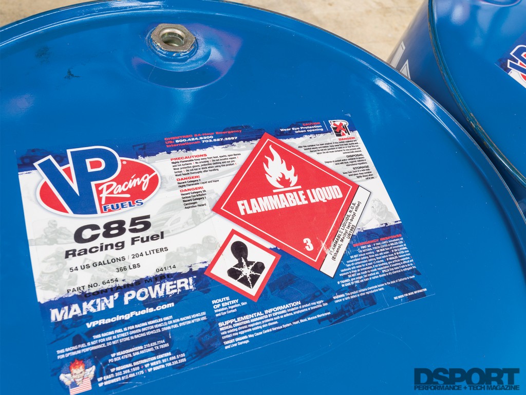
We’ve seen improved performance from racing fuels with MTBE additives. However, not every vehicle is equipped with a MTBE compatible fuel system. If your vehicle is not equipped for MTBE, fuel starvation could occur.
When you change over to a fuel with more alcohol content (E85 or methanol), the issues with chemical compatibility become exacerbated. For these applications, hoses with a PTFE or Teflon inner lining are considered a must by many as they will not be affected by the alcohol content. While a number of different performance hoses may use the same inner hose material, this doesn’t mean that they will offer the same performance. Smooth-bore PTFE/Teflon hoses from different manufacturers may both be offered as -8AN lines, but one may have 20-percent more flow area than another. Inner-hoses may also have external or internal convolutions to improve bend radius and reduce production costs. External convolutions with a smooth bore do not hamper the flow performance of the hose. However, inner hoses with internal convolutions will reduce flow due to turbulence. In many cases, a -8AN inner smooth bore hose will deliver the same flow as a -10AN internally convoluted hose. In addition to costing significantly more than rubber-based hose, the PTFE hoses cannot be assembled in the field by the end user. Instead, these hoses require professional assembly with crimp on fittings done by a specialized machine.
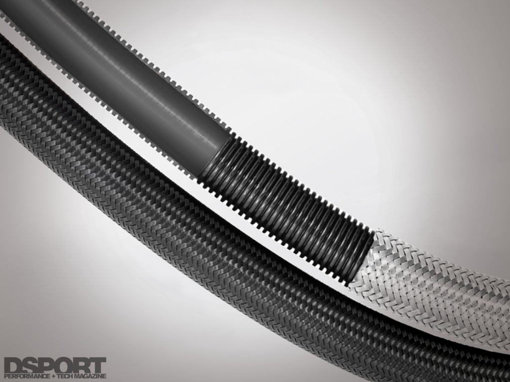
Smooth bore hoses with external convolutions do not hamper the performance of the hose the way the same sized hoses with internal convolutions would.
Not Just Bigger, Better
Does it fit and will it flow enough? While proper fitment and enough flow capacity to meet the maximum horsepower demands of the engine are two elements of an “ideal” fuel injector, there are so many more elements that are often overlooked. Fuel compatibility, low-duty- cycle performance and high-duty-cycle performance will all have a major impact on injector performance.
Nearly a decade ago, a discovery was made that a Bosch injector line originally intended for compressed natural gas (CNG) delivered some impressive performance when used on gasoline applications. These high-impedance injectors offered high flow rates in the 2,200cc/minute range to support some serious power per cylinder. Best of all, these injectors could be run at very low duty cycles to allow them to idle on small displacement engines. The popularity of these injectors spread like a wild fire fed by a strong Santa Ana wind. While the majority of users were experiencing great results, there was a major issue to be discovered. These CNG injectors had polymer internals that were not compatible with MTBE, a common additive in some racing fuels and pump gas. Using a fuel with MTBE with these injectors would cause the peak flow rate to drop dramatically as the polymer internals would swell to not allow full flow through the injector. Today, the aftermarket has responded by offering higher flow rate injectors with MTBE compatibility. This is accomplished by using stainless steel internals as opposed to polymers.
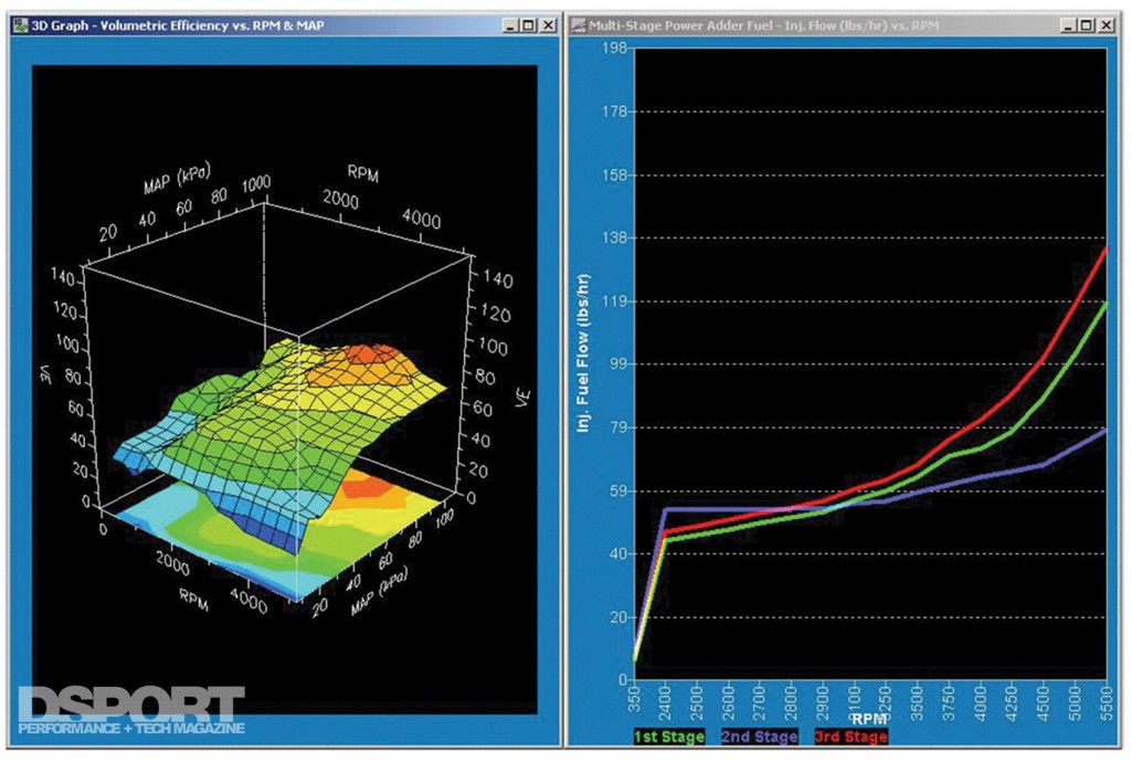 Modern fuel injectors offer improved high volume control and refinement not previously possible. This level of control makes tuning at or near the maximum rated duty cycle a reality.
The RB26DETT engine in our Project RH8 started out at 280 rated horsepower. The 2,569cc six cylinder featured six 428cc cylinders being fed by six 440cc/min injectors. Today, the 2,599cc engine produces 1,500 flywheel horsepower being fed by six 2,200cc/ min injectors. Each cylinder has only grown by 5cc in displacement yet the injectors have FIVE TIMES the flow of the factory injectors. Since the modified engine makes the same (or even less) horsepower at idle as before, it’s essential to be able to control the larger injector to a lower duty-cycle that will deliver the same amount of fuel as an injector that’s one-fifth its flow rate. This shows why low-duty cycle performance is essential to a high-performance injector.
You may have read that you should try to choose an injector sized to only run a maximum duty cycle of 85-percent at your target horsepower load. What happens if you run the injector at 87-, 90-, 95- or Heaven-forbid 100-percent? Doing so would make a tear in the space-time continuum, creating a wormhole that would suck the galaxy into a different dimension. Well, not exactly. Let’s assume that injectors deliver a percentage of their flow that matches the duty cycle (this linear relationship is not the case, but it serves to simplify the example).
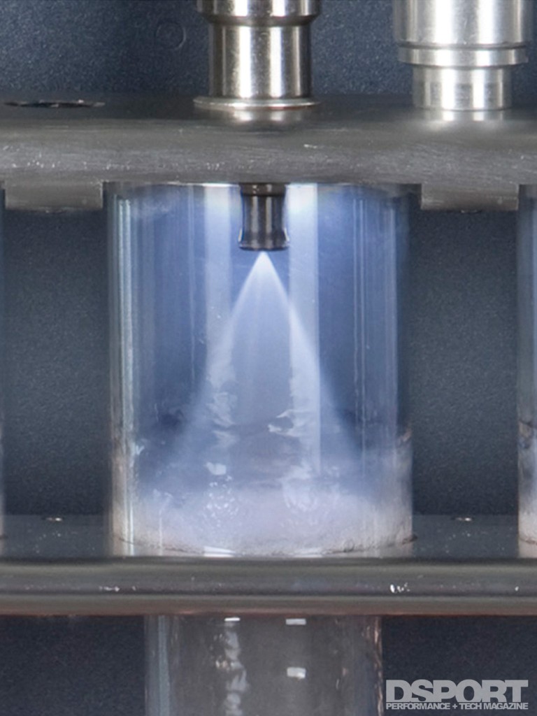
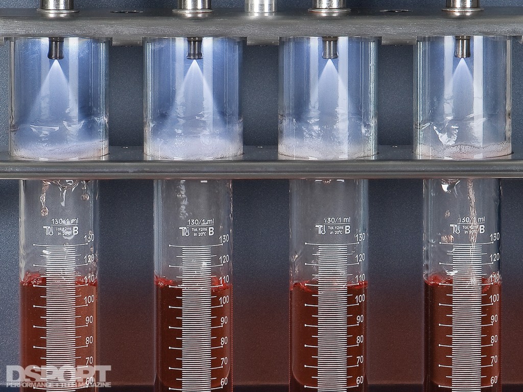
An injector’s spray pattern aims to maximize the atomization of fuel while ensuring that adequate fuel volumes reach the combustion chambers.
At a duty-cycle somewhere between 86- and 95-percent you’ll find that the injector is no longer in a controlled state. The injector simply defaults to fully open. Let’s say that this happens at an 87-percent duty cycle. Assuming the engine was at the desired air-fuel ratio when the duty cycle was at 86-percent, it will now see an additional 15-percent fuel delivered when the ECU tries to put the injector at 87-percent. This will cause the A/F ratio to go richer, which will lead to reduced performance. For an injector capable of superior control at higher duty cycles, the situation is different. Apply this example to an injector going from a 94- to 95-percent duty cycle. In this case the amount of additional fuel is just about 5-percent. This 5-percent additional fuel is much less likely to have an impact on performance. When an injector can be operated at a higher duty cycle before going “static,” there is an advantage. This is especially true on applications where an injector must operate at 90-percent to meet the horsepower demands.
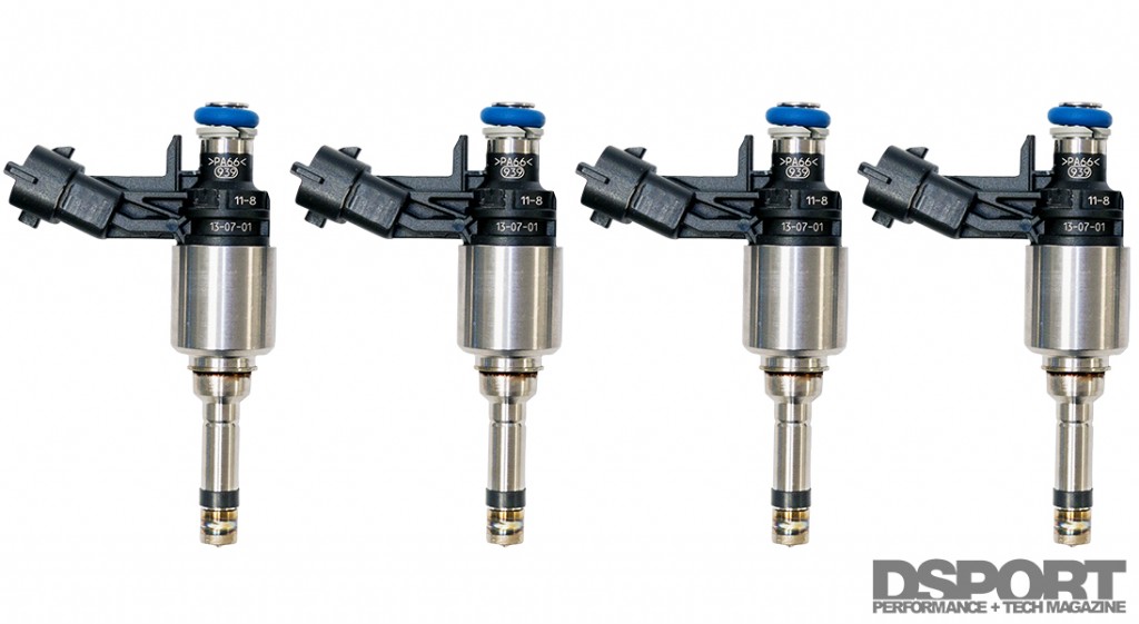
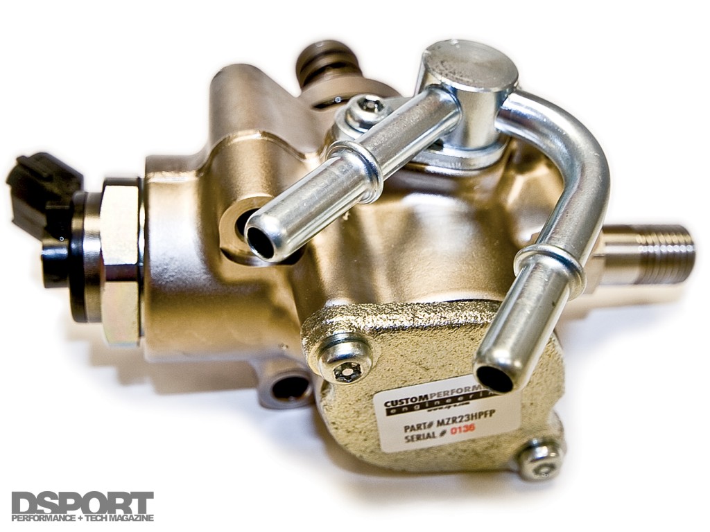 Direct injection technology uses mechanical fuel pumps and specialized fuel injectors running extreme fuel pressure levels (approximately 1,600 psi). While incredibly efficient, this relatively new technology has limited aftermarket support, save for a few like these from CP-E and mountune.
Fuel Tech 301
After mastering an understanding of Fuel Tech 101 and Fuel Tech 201, you should be knowledgeable enough to ask the right questions when designing your high performance fuel system. With OEMs pushing the use of brushless fuel pumps and direct injection fuel technologies, it’s only a matter of time before the aftermarket has more solutions in this arena. As soon as the aftermarket is ready, DSPORT will be there with a Fuel Tech 301 to deliver the goods.


