
Conditions:
• Head(s) on the engine • Centerline Cam Degree Method
How to Degree Camshafts, Preparing the Engine for Cam Timing Measurement
1. Make sure that all of the spark plugs have been removed from the engine. This will make it easier to rotate and position the crankshaft.
2. Use a factory service manual to disassemble the front of the engine to the point where you can see the timing marks for the camshafts and the crankshaft.
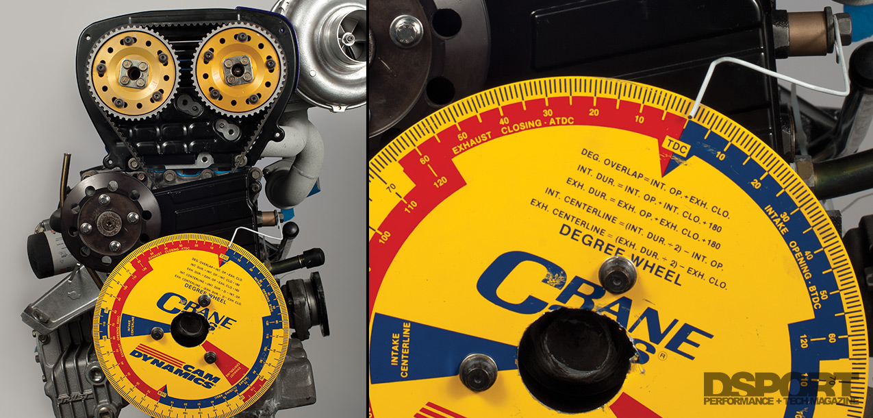
3. Test fit the degree wheel to the engine. If you have an aftermarket damper, it should have three holes that exactly match to the degree wheel. If your balancer does not have these holes, you can also remove the factory balancer and affix the degree wheel directly to the crankshaft snout with the crankshaft bolt and spacers.
4. You will need some way of being able to rotate the crankshaft. Since our degree wheel is held to the ATI Super Damper with the three bolts, we elected to bore a large hole in the center of the degree wheel to allow us to affix a socket on the crankshaft bolt.
5. If the engine has a flywheel installed on the crankshaft, you can also use a flywheel turning tool that allows you to rotate the engine.
Locating Top Dead Center for Cylinder Number One
1. Rotate the engine until just before the timing mark lines up. This occurs on both the compression and exhaust stoke. During the compression stroke, neither the intake nor the exhaust valves will be lifted. This is what you want to see. If the exhaust valve is lifted then you need to continue to rotate the crankshaft another revolution until it isn’t.
2. There are usually some type of timing marks on the camshafts and crankshaft that indicate the engine is at Top Dead Center for cylinder one on the compression stroke. Check to see that these marks are also close to being lined up.
3. Now, slowly rotate the crankshaft until all the factory timing marks at the crankshaft line up. The marks at the camshafts should also be lined up at this point too. To verify that the piston is actually at the top of its travel, a piston-stop tool can be used. This tool should be threaded by hand into the spark plug location until slight contact is made with the piston.
4. If you are at top dead center with the piston-stop tool in place, you will be unable to rotate the crankshaft in either the forward or reverse direction. With light effort check to see that the crank cannot rotate a slight amount in either direction. If it does move, remove the piston-stop tool and repeat the process again. NEVER leave the piston-stop tool in place while rotating the engine as it may interfere and bend the valves.
5. Set the engine at top dead center for the compression stroke on cylinder one.
6. Remove the piston-stop tool.
7. Affix degree wheel to crankshaft.
8. Make a pointer and set to “TDC” on the degree wheel. A pointer can simply be made from a coat hanger or similar gauge solid wire. Cut the hanger so that you have a length of wire long enough to bend into a pointer. On one end, affix the wire to some location on your engine with a bolt and washer. Use pliers to bend the wire so that it points over TDC on the degree wheel. Check to see that the wire doesn’t move and allows the crankshaft to be rotated.
9. Note factory timing marks and record any differences. You may want to make a new timing mark on your balancer that matches with the factory fixed timing mark.
10. Now you are ready to degree the intake and exhaust camshafts.
Finding Intake Centerline
Degreeing the Intake camshaft
1. Find the camshaft manufacturer’s intake centerline specifications on the camshaft card or in the catalog. This number represents the point in crankshaft degrees where the intake valve is lifted to its highest point.
2. Rotate the crankshaft until the intake lobe begins to open the intake valve. Remember that you must always rotate the engine in its standard direction of rotation. Never go the opposite way as it may create slack in the timing belt or chain that will produce incorrect readings.
3. Once the intake valve begins to open, look at the degree wheel and see where the “intake centerline” region is located. Rotate the crankshaft until the 90~100 degree range before the intake centerline band.
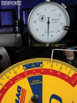
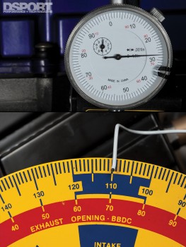
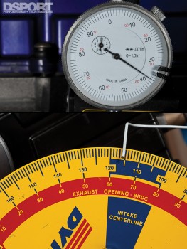
4. At this point, a dial indicator must be mounted and set up to measure the valve movement at the intake valve. The gauge is not going to be used for an actual measurement, only to locate the point at which the maximum lift on the valve occurs.
5. Set up the dial indicator so that it shows at least .100” in measurement.
6. Now here is the part that requires finesse. Slowly rotate the crankshaft while watching the dial indicator. Once you get to 5 degrees before the manufacturer’s specified intake centerline, record the values indicated on the dial indicator.
7. Rotate the crankshaft a single degree and record the dial indicator numbers. Repeat until you are five degrees past the manufacturer’s intake centerline specification.
8. During this 10-degree rotation, the needle of the dial indicator will move in one direction (while the valve was still being lifted), then it will stop (when the valve reaches peak lift) and finally it will change direction (as the valve started to close). This should all occur as you rotate the crankshaft from 5.0 degrees before to 5.0 degrees after the manufacturer’s specified intake centerline.
9. The point when the needle stops (or the value is the smallest recorded) is the actual intake centerline of the intake camshaft in the engine.
10. Note if the measured value is different than the manufacturer’s specified value.
11. If you wish to set the intake cam timing to the cam manufacturer’s specified value, an adjustable cam sprocket will allow you to dial in the camshaft timing to the manufacturer’s specification.
12. After adjustments are made to cam timing via cam sprockets, repeat steps 2 through 10 until the cam is “Zeroed” properly.