Back On the Dyno
With the car once again operational, we decided to get back on the dyno so that we could evaluate some more performance parts. Our plan was to first, recalibrate the A’PEXi Power FC maps to be optimized with the new load points addressed by the Holinger 6-speed. With Eric Hsu of XS Engineering on the laptop and our car strapped to their four-wheel dyno, we began our tuning session. Unfortunately, the engine wasn’t responding to the new fuel maps. Something was wrong with the vehicle and our tuning session was cut short and XS Engineering scheduled a full diagnostic for the following day.
 The diagnostic session determined that the engine was making very good compression and that the charge air system was free of leaks. Everything checked out ok, with the exception of the air flow meters. Upon inspection of the meters, a significant amount of oil film coated the entire inside of the meter. As a result, the meter’s sensitivity was most likely affected. The cause of the oil had to be identified.
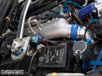
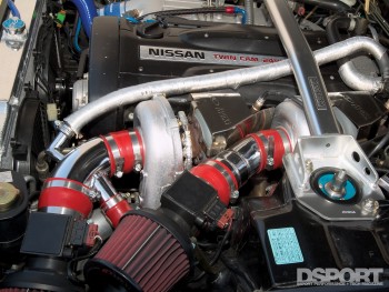
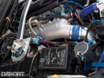
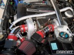
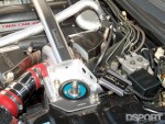
Upon inspection of the crankcase ventilation system and turbocharger system, we believe that we’ve identified the culprit. Our RB26DETT crankcase ventilation system is currently identical to the factory configuration. Under vacuum, the positive crankcase ventilation (PCV) valve is held open by manifold vacuum. Crankcase vapors are sucked through the intake manifold and are eventually fed into the combustion chambers. When no vacuum is present or the intake manifold is in a boost condition, the PCV valves closes. With the PCV valve closed crankcase pressure gets directed to the breather fitting on the top of the passenger side valve cover. This breather fitting attaches to the intake pipe feeding the turbocharger by way of a 3/4-inch hose. When the turbocharger is ingesting large amounts of air, a vacuum is created in this 3/4-inch hose. Along with the crankcase vapors a small amount of engine oil becomes drawn into the turbochargers air intake pipe. Normally the small amount of oil drawn through the intake system would not amount to a problem. Due to a special circumstance on our application (the absence of a blow- off valve), this oil would be one half of the recipe needed to foul our air flow meters. The other half of our recipe for disaster would require that air flow would have to become reversed in the intake air pipe. Normally, this would never be seen, however since our turbocharger system lacks a blow-off-valve, that’s exactly what we experienced. Since we are using IHI RX6B turbochargers, no blow off valve is required. The IHI RX6B ball-bearing turbochargers are built tough enough to endure the surge effects encountered when the throttle is closed under boost. It’s our belief that our current configuration allows for oil to be drawn into the intake pipe when the turbos are ingesting large quantities of air and then this oil is blown on to the air flow meters when the throttle is closed under boost.
The Solution
 The simplest fix would be to add a blow-off-valve to our turbocharger system. However, since we are using an L-Jetro or Mass Air Sensor equipped vehicle, it’s imperative that the blow-off is directed back into the turbos. For the blow-off-valve to operate at its best efficiency its optimum location is close to the throttle bodies. The problem is that this location results in a bypass hose that must be routed across the entire engine. It’s a possible, but very cosmetically- challenged fix.
Another possible fix would be to eliminate the Mass Air Sensors and convert the vehicle to D-Jetro or Speed- Density. A’PEX Integration offers a number of its Power FC plug-and-play engine management systems in both L-Jetro and D-Jetro applications. The GT-R is one of the applications where both systems are offered. The majority of high-horsepower, RB26 powerplants in Japan have been converted to D-Jetro. D-Jetro conversions will generally provide improved throttle response while sacrificing a small amount of the ECU’s ability to compensate for air-density and air-flow variations. What we like about this solution is that anything goes on designing an air intake system. With the air flow meters in place, the size of the air flow meters dictates the maximum size of the inlet piping to the turbocharger. Without air flow meters, the sky’s the limit.
A D-Jetro conversion on an RB26 is not without its challenges. The factory’s individual throttle body intake system doesn’t allow for a pulse-free and consistent manifold air pressure signal. If the factory throttle bodies are left in place, A’PEX Integration recommends that the MAP signal be taken from the two center cylinders (3&4) be tapping fittings into the intake manifold below the throttle bodies. Another popular solution in Japan is to completely eliminate the factory throttle bodies and convert the system to a single throttle body. We’ve contacted VeilSide that manufacturers such a kit and they are checking to see if they have time to put together another custom intake and throttle body for our GT-R. If VeilSide is unable to get us an intake manifold in time, we may try to get a custom piece built.
The Future
 Data acquisition is key to making informed choices. Recently, we obtained an FC Datalogit to record engine data from our A’PEX Power FC. In addition to recording every factory sensor seen by the Power FC, the FC Datalogit also has four additional 0-5V analog channels that can also be datalogged. Our plan is to use Channel 1 and 2 to read air-fuel ratios thanks to the addition of an AEM dual-channel UEGO system. Channel 3 will be used to record EGT from an A’PEX electronic EGT meter (the A’PEX gauges feature a 0-5v output just for this option). Channel 4 will either be used to record barometric pressure (by adding a 1-bar MAP sensor) or it will become a secondary channel to record an additional EGT or Boost input (i.e. boost pressure before versus after the intercooler or EGT before versus after the turbine).
Once we sort through these issues, it will be time to dyno test our ACPT carbon-fiber driveshaft, a Hyper Ground System and possibly a set of drop-in A’PEX Integration camshafts. In this process, we plan to get out to the dragstrip and see what numbers can be laid down with the stock engine.