
Giant peak horsepower figures made on race gas make for great headlines. Just the mention of a “1000-horsepower Supra”, “740-horsepower WRX” or “500- horsepower EVO” draws attention. While peak horsepower numbers are real and exciting to any enthusiast, these high- caliber numbers tend to distort the total performance picture. This picture becomes blurred since few enthusiasts understand the performance difference attainable between 91-octane pump gas and 117-octane racing fuel. The fact is that swings of anywhere from 50 to 500 horsepower can be seen on turbocharged vehicles when the fuel is changed from pump gas to race gas. While the performance difference between pump gas and race gas can be night and day, the parts selection made by some tuners also impacts total performance. By losing sight of the total performance picture and by focusing on just the peak horsepower number, some tuners chose combinations that generate impressive peak horsepower numbers while sacrificing performance across the rest of the powerband. It is those parts that lose five to 10 horsepower from idle to 7000 rpm for a gain of three peak horsepower at 8000 rpm. We will focus on the total performance picture as we seek out maximum total performance, maximizing all of the area under the curve on both pump and race gas.
Text & Photos by Michael Ferrara
Project RH9 GT-R: Speed Density Conversion
Last month, we explained the problem we were encountering with oil contamination of the air-flow meters. It was causing us to literally chase our tails on the dyno as air-fuel ratios were very inconsistent from run to run. We mentioned the possibility of converting from the factory-style mass-air metering to a speed-density configuration.
Fortunately half of the necessary parts were readily available. XS Engineering had a D-Jetro (Speed-Density) A’PEX Integration Power FC in stock. As for the other half of the parts, our plan of swapping to a single-throttle-body setup (in place of the factory individual throttle body configuration) would have to be delayed. VeilSide USA did not have the intake manifold and throttle body that we needed in stock. According to VeilSide USA, each of the intake manifolds is hand built and they estimated that the wait could be anywhere from a few weeks to a few months. We would be using the factory individual throttle body setup.
| Mass Air (L-Jetro) | Speed Density (D-Jetro) |
|---|---|
| (+) Extremely Accurate Altitude Compensation | (+) Restriction Free |
| (+) Self Compensation* for addition of aftermarket parts | (+) Superior Boost Response |
| (-) Restrictive Element in Intake Tract | (+) No limit to air filter plumbing |
| (-) Decreases boost response on applications where meter is upstream of turbo | (-) No Self Compensation; Retuning required with parts changes |
| (-) Boost pressure/Vacuum leaks cause engine to run excessive rich | |
| (-) Engine may barely run when I/C pipe becomes disconnected | |
| (-) Blow-off-valve or Compressor bypass valve must have its flow recirculated |
–
This introduced a new challenge. According to XS Engineering and a few GT- R owners, the D-Jetro Power FC has some “driveability” issues when used with an individual throttle body setup. Unlike a single-throttle body, plenum-type intake manifold, the individual throttle bodies do not offer a stable and smooth vacuum or pressure signal. Instead, the signal from one of the individual throttle bodies provides a very “pulsey” and erratic output. To reduce this effect, A’PEX Integration engineers recommend that two separate manifold air pressure (MAP) sensors be used; one of the MAP sensors reading a signal from cylinder number three and one reading a signal from cylinder number four. While this method accurately reads the signals in each of these cylinders and is obviously better than using the signal from a single cylinder, we believed that the signal would still be a bit choppy. Since we were looking for a smooth as glass idle and repeatable performance, we needed a very stable signal. In looking for this stable signal, we focused on the factory balance tube (a tube that reads the pressure and vacuum from all six cylinders). It was our belief that the signal from the balance tube would be very stable. Since HKS uses a single MAP sensor hooked up to the factory balance tube when installing its engine management system, we decided our hunch was definitely worth a try.
Anytime you disregard the installation instructions for an engine management system, you assume a giant risk. In our case, the risk paid off. The MAP sensor signal obtained from the balance tube has proven to be very stable and we have a smoother idle, better throttle response and better driveability than we ever experience with our Mass Air setup.
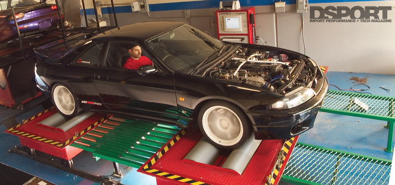
Dyno Time
 With the swap from a Mass-Air Power FC to a Speed-density Power FC, we needed to start from square one with regards to tuning. Our plan was simple. Retune the Power FC, then dyno-test the ACPT carbon-fiber driveshaft, a set of HyperGrounds and the A’PEX Integration Super Grounding System. With the addition of the AEM dual-channel UEGO system and the FC Datalogit, we looked forward to a smooth and trouble-free tuning experience. Unfortunately, things didn’t go exactly as planned.