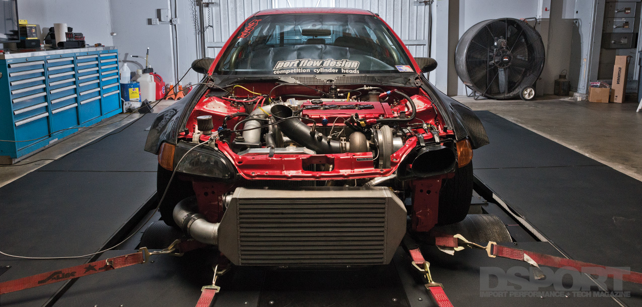
You guys are probably the only ones to have ever measured and discovered that issue. This is a statement that we are hearing more and more as we delve into the uncharted territory of extreme Honda performance. While people have been racing boosted B-series Honda engines for nearly 20 years, the engineering level of the development has been predominantly “grassroots”. The issues that we are uncovering while attempting to extend the life of a 1,000whp boosted B-series won’t be found under a forum thread. Instead, DSPORT is finding the limits and solutions using engineering, accurate measuring, precision machining and scientific engine development. In this installment, we’ve not only conducted some scheduled upgrades, but we’ve also put some solutions that should remove the weak links discovered during our first tear down and inspection.
Text by Michael Ferrara // Photos by Jun Chen
TEARDOWN TIME
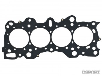 After a couple unfavorable attempts to get the Civic down the track for a full-power pass, we got the Civic back in our shop to conduct an inspection. Based on the datalogs from the MoTeC engine management system, the head gasket seal had been compromised. Thus, we pulled the engine for a complete teardown and analysis before any catastrophic damage occurred.
HEAD LIFT AND COMPROMISED SEAL
 While the pistons showed no signs of encountering detonation, the extreme cylinder pressures that result when 620 lb-ft of torque is generated by a 2.0-liter engine at 45psi of boost pressure appear to be more than the off-the-shelf 8740-alloy ARP head studs (208-4303 for GSR or 208-4601 for B16) could handle. When torqued to 80 lb-ft (about 10 lb-ft above the recommended spec), the 8740-alloy studs provide enough clamping force to keep the head in place at 500 lb-ft of torque. However, these studs fell just a bit short of providing enough clamping force to eliminate head lifting when torque eclipses the 600 lb-ft mark. Fortunately, ARP offers a higher strength Custom Age 625+ alloy for those building engines that develop extremely high cylinder pressures. Considering that we are producing nearly six times the factory torque output of the engine, you can be sure that our cylinder pressures are definitely in the extreme range.
TORQUE IT UP!
 For the ARP CA625+ head studs to deliver additional clamping force, the torque on the stud must be increased. Previously, we were running the standard 8740-alloy ARP head studs at 80 lb-ft of stud torque, the new CA625+ studs can be installed at 90-to-100+ lb-ft. Accounting for the difference in fastener diameter (the 8740-alloy studs feature a 0.5mm to increase preload by 5.0 percent for a given torque), we will now have 35 percent more clamping load at 100 lb-ft of stud torque. That means that 35 percent more cylinder pressure (torque output) from the engine can be realized before the head will lift. The CA625+ alloy’s exceptional strength means we will have a hard time exceeding the yield strength of the stud.
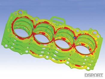 When deciding to go the ARP CA625+ route, the cylinders must be honed with a torque plate. Based on our measurements of a wet-sleeved, open-deck Honda B-series block, there is way too much additional distortion when the head stud torque is increased from 80 lb-ft to 100 lb-ft. This may not be an issue or less of a factor on Darton MID sleeved blocks or DART closed-deck blocks (we’ll test both in the near future). If the desire is to keep the cylinders as round as possible for maximum ring seal and performance, one must always select the exact head studs and head gasket that you’ll be using before you have the cylinders honed to size with the torque plate in place. The head gasket (you’ll need a second head gasket for the actual engine assembly) must be placed between the torque plate and block before the CA625+ head studs are torque to 90-to-100 lb-ft. Then, the honing operation can take place. Following this procedure corrects for any additional distortion to the cylinders that results from the increase in head clamping.
THREAD THE NEEDLE
 In the case of the Honda B-series block, high torque values for the head studs increases the risk of pulling the threads out of the aluminum block. To reduce this risk, it is imperative that all of the threads in the block are properly cleaned and chased with a tap before the studs are installed into the block. After cleaning the threads on the studs, a very light mist of a moisture-displacing light oil like (Royal Purple Max Film or WD-40) on the lower threads will address any moisture and reduce the oxidation of the aluminum threads. After the block and studs are properly prepped, a hex socket and ratchet should be used to hand tighten the studs into the block. Before putting the head gasket and torque plate in place, be sure to coat the head studs upper threads with ARP Ultra-Torque fastener assembly lube.
HEAD GASKET, WIRE O-RING OPTIONS
[pullquote]WE OPTED TO TRY AN ALTERNATIVE THAT DOESN’T REQUIRE ADDITIONAL MACHINING OF THE BLOCK[/pullquote]On the subject of head gaskets, the Golden Eagle gasket (which is a modified OEM Honda gasket) didn’t appear to be the cause of our diminished cylinder seal. Instead, it appeared to simply be the lifting of the cylinder head under extreme cylinder pressures that compromised the seal. Once the head lifted, high temperature combustion gasses started to affect the cylinder deck surface. In retrospect, we may have been able to extend the life of this head gasket by doing a re-torque of the head studs after our engine break-in session on the dyno. After all, nearly all of the 1,000 horsepower B-series engines that rely upon open deck sleeves frequently re-torque the standard ARP 8740-alloy head studs. Some also use a wire O-ring or stepped deck (sleeves 0.002″ higher than the rest of the deck) to increase the seal pressure around the cylinder. While using an O-ring or stepped deck with the Golden Eagle head gasket could have been one route, we opted to try an alternative that doesn’t require additional machining of the block.
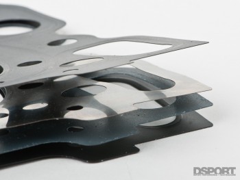
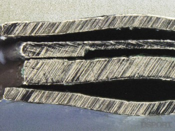
JE Pistons now offers its Pro-Seal head gaskets for the B-series VTEC. The 0.033″ thick gasket features a four-layer multi-layer-steel construction (as opposed to the 0.026″ thick, three-layer MLS factory Honda gasket). The four-layer design also incorporates a folded stopper around the cylinder to provide an effect similar to a wire O-ring. The fold makes a 0.005″ thick ring that’s about 0.045″ in width right around the cylinders to keep combustion pressure inside the cylinder. The gasket’s construction appears to be top notch and the outer coating is one of the best that we’ve seen. This gasket and the ARP CA625+ alloy studs should have no issues keeping our new Port Flow Design prepared GSR cylinder head in place.
HEADS-UP! BYE BYE B16, HELLO GS-R
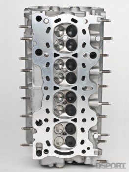
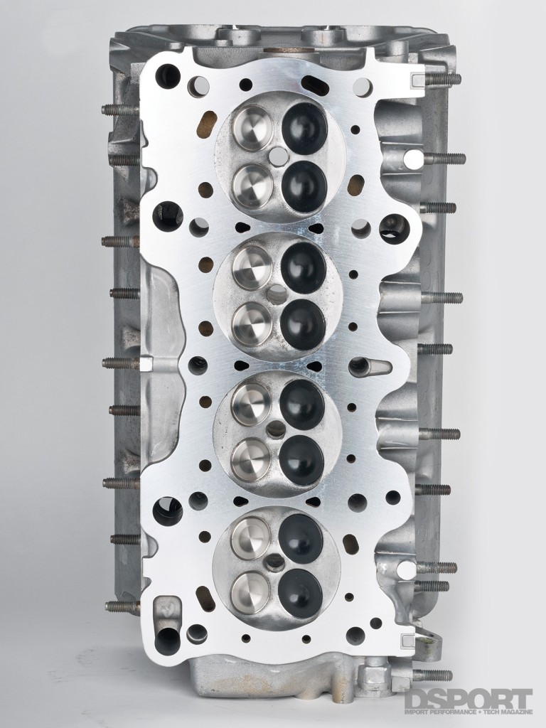 While B16 cylinder heads are easier to find than GSR heads, many are older, tired and abused. Since B16 heads were the cheapest solution to building a budget LS/VTEC engine, a surplus of B16 engines sit headless in junk yards and shops across the world. Unfortunately, many of those that purchased B16 heads have subsequently ruined the heads with way-too-big do-ityourself porting or by excessively milling the deck of the head to increase compression (instead of just buying the proper pistons). We originally chose the B16 head because that’s what we could find at the time. When Tom Fujita at Port Flow Design told us that he located an unmolested GSR head, we jumped at the chance to swap over.
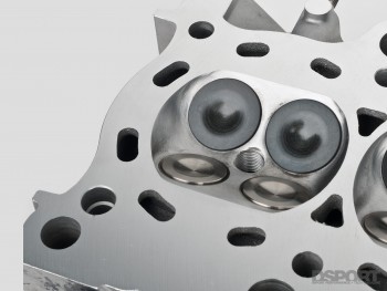
[pullquote]IF YOU NEED TO PRODUCE MAXIMUM RELIABLE POWER FROM A BOOST B-SERIES, FIND A GSR HEAD[/pullquote]For boosted applications, the GSR cylinder head is simply the better head for the job. While there is a difference in the layout and geometry of the ports, it’s really the GSR’s combustion chamber design that makes it the better choice for boost. The GSR head is superior since it allows the engine to take advantage of squish (increased turbulence and mixing) in the cylinder thanks to the GSR’s quench pads. When the piston-to-quench-pad clearance is optimized to the 0.033-to-0.040-inch range on a boosted B-series Honda, good things happen. As the piston approaches TDC on the compression stroke, the air/fuel mixture is squished out of the quench areas and driven into the center of the cylinder under significant turbulence. Improved mixing and a reduced distance of required flame front travel mean less ignition timing advance is needed to produce peak torque and power. Less ignition timing reduces the likelihood of engine-damaging detonation. If you need to produce maximum reliable power from a boosted B-series, find a GSR head. While exhaust manifold flanges are identical between B16 and GSR heads, the intake flange and bolt position is different. Fortunately, our Skunk2 intake features a dual bolt pattern to fit either.
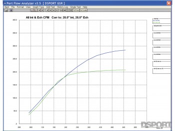 While the GSR is a great flowing cylinder head, we took the opportunity to make it even better. Tom treated the GSR to a “pocket port” before installing new Supertech valve guides, Supertech stainless-steel intake valves, Supertech Inconel exhaust valves, Supertech springs and Supertech retainers. Tom also shimmed up the springs to deliver additional seat pressure. Higher seat pressures help keep the valves closed at high boost pressure and exhaust backpressures. Tom also took the time to flow both our fully-ported B16 cylinder head and this pocket-ported GSR head. The GSR head outperformed the B16 head significantly in the mid-range valve lift range. This indicates that flow velocities are superior on this GSR head. High velocities improve cylinder filling and produce more power. More power, better response and a reduced likelihood of detonation. What more could we ask for?
With the head ready for action, we opted to set the pistons at zero-deck (flush with the surface of the block). This would allow us to use the 0.033″ thickness of the head gasket to establish the quench distance. Setting it to the small side of the range should only be attempted if the design of the piston and the piston-to-wall clearance establish minimal piston rocking. Otherwise, a short skirt piston set up with excessive piston-to-wall clearance might rock itself into the quench pad on the GSR head at high RPMs. If you have low-quality pistons or sloppy machine work, you’ll always need to run larger clearances.
HEAD SEALING, VALVES LEAKING
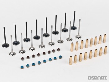 It’s been said that solving one problem often leads to uncovering the next. In the case of our Honda B-series build, the ARP CA625+ head studs and JE Pro- Seal head gasket appear to be a viable solution to improve sealing at extreme cylinder pressures. Unfortunately, the story doesn’t end there. We discovered that the open-deck sleeved B-series block exerts so much pressure on the cylinder head (with the head stud torque at 100 lb-ft) that the valves in cylinder #1 (especially the intake valves) will begin to leak. The reason has to do with the B-series head design. The Honda B-series head has very little supporting overhang on its cylinder #1 side while a good amount of additional material extends beyond cylinder #4 (hence #4 doesn’t have issues). This lack of material beyond the edge of the head makes it prone to higher stresses. These high stresses upset the sealing of the valves against the valve seats.
[pullquote]AS THE RINGS “BREAK-IN” WE EXPECT TO SEE THE SETTLED LEAKDOWN NUMBERS DROP ANOTHER 5-TO-10 POINTS[/pullquote]On cylinder #1, we noted zero leakage through the valves with the head torqued to 70 lb-ft. As we increased the head stud torque to 80-, 90- and 100-lb-ft, an audible hiss could be heard through the intake. Higher head stud torque led to higher leakage. With the head stud torque set to 100 lb-ft, we recorded 35 percent leakdown on cylinder #1 while the rest of the cylinders checked in at about 10 to 12 percent. After the engine started and heat cycled three times, we noted that the valve sealing improved. The intake hiss was barely audible. We measured just 18 percent in cylinder #1 before beginning our tuning session on the dyno while the rest of the cylinders were still in the 10- to 12-percent range. To verify that we didn’t have an issue with the valves or the head, Port Flow Design recut the valve job and reground all the valves. The results were identical. We even duplicated the issue with the B16 cylinder head. We plan to see if the valve seal continues to improve over time as the running of the engine reduces pent-up stress concentrations. As the rings “break-in” we expect to see the settled leakdown numbers drop another 5-to-10 points.
MORE ISSUES…
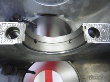
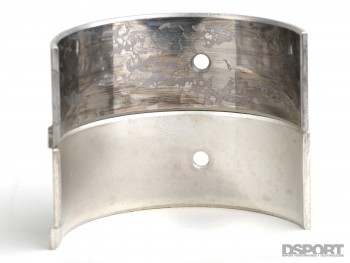 When horsepower from an engine is increased on the order of sevenfold, unexpected problems will surface. While head gasket sealing challenges are nothing new for high-output engines, we did discover some other issues. After just 12 full-power dyno passes and three separate attempts to set up the launch strategy (two-step and anti-lag), all of our Honda rod bearings showed evidence of surface fatigue while we also noted slight piston-to-valve contact on our exhaust valves (in the original B16 head). Extreme surface fatigue was evident on the rod bearings as about 80 percent of the Babbitt layer was cracked and flaked off. Generally, this type of bearing failure is the result of overloading. Lugging, detonation or overfueling can all cause this problem, as well as simply exceeding the load capacity of the bearings. We opted to try WPC treatment on a set of ACL rod bearings to see if this remedies the issue. Since the GSR head will require a completely different timing curve, we also plan to retune our timing curve which should reduce the chances of detonation.
 Since we checked the piston-to-valve clearance on the engine during its original assembly, the exhaust valve to piston contact is not from an inadequate amount of static clearance. Instead, we attribute the issue to either valve float or sticking of the valves in the guides. Considering that we also found a cracked exhaust valve guide that looked to be cooked, we believe that the EGTs rose too high when the anti-lag system was being dialed in. This excessive heat caused the valve guide clearance to get too tight. As a result, the exhaust valve was likely sticking open on its return to its seat. This caused it to be clipped by the piston. To avoid this issue in the future, we decided to give up on using the anti-lag. Instead, we’ll build boost through a two-step. To add an extra measure of protection, Tom at Port Flow Design trimmed back the portion of the exhaust valve guide that protrudes into the port. This should help reduce the amount of heat transferred to the exhaust valve guide through the exhaust. Less heat means less likelihood of having the valve stick or seize in the guide. While this isn’t a recommended modification for a street car that is looking to run for 100K miles before a rebuild, it shouldn’t cause any issues on our drag Civic.
REFRESHED ENGINE, SUPPORTING CAST
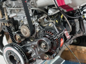 You may recall that we wanted to increase our fuel pump output by upgrading to a 16V lithium battery and 18V alternator. We had to modify the OEM upper alternator bracket to fit the new Powermaster alternator. The Voltphreaks battery fit in the factory location without issue. The charging system now runs at 17.5 volts, instead of 13.5 volts. This additional 4.0 volts significantly increases the output of the fuel pump and ignition system. In fact, if the fuel pump receives 17.5 volts at idle, fuel pressure cannot be set below 55 psi. Fortunately, the Fuelab electronic regulator communicates, controls and regulates the voltage to the Fuelab pump. As such, the fuel pressure can be set to 43.5psi or lower since the regulator is telling the pump to lower its speed. While we have yet to make a full-power pass to redline, initial indicators show that bumping up the maximum available supply voltage to the fuel pump solved our fuel supply issue.
[pullquote]WE BELIEVE THAT OPTIMIZING THE CAM TIMING SHOULD BE ABLE TO MAKE UP FOR ANY LOSSES[/pullquote]In addition to meeting our massive fuel delivery demand, we also wanted to improve the boost response setup of our combination. To do this, we changed to a small 1.10 A/R turbine housing (previous was 1.25 A/R). During break-in, we wanted to check when full boost could be reached. Previously, our target boost of 43.5psi couldn’t be realized until about 8,000-8,100 RPM with the 1.25 A/R turbine housing in place. With the 1.10 A/R housing, we can reach 43.5psi of boost pressure at 7,000 RPM. Of course, a smaller A/R turbine housing may choke off some top-end performance, but we believe that optimizing the cam timing should be able to make up for any losses.
DARTON MID AND DART SOLUTIONS
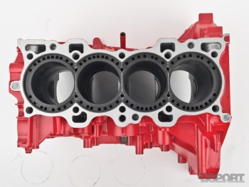 As we go to press, the Civic has completed its break-in session on the dyno and tomorrow we’ll begin the power pulls. While the engine combination reached its intended power target, cylinder head sealing and surface fatigue of the rod bearings have presented new challenges. While the WPC treatment of the rod bearings will likely solve our bearing issue, our solution to the sealing issue has only revealed more shortcomings of an opendeck, sleeved Honda B-series. With the writing on the wall large enough to be read by the legally blind, it only makes sense that other options are explored. Hence, we’ve opted to send our spare GSR block to Darton for the installation of some MID sleeves. It’s our hope that the integrated deck design of highquality Darton sleeves will perform better than our off-brand wet sleeves. At the same time, we also want to explore the performance of a DART B-series block. These heavy-duty aftermarket blocks feature Darton sleeves, a closeddeck, steel main caps and extensive ribbing for additional strength. Best of all, they accept all Honda B-series cylinder heads and hardware. Our goal is to find the best foundation and combination for a 1,000-plus wheel horsepower Honda B-series that can deliver the goods for an entire racing season without breaking a sweat. Next month, full-power pulls!


