Bearings and Clearances
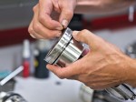
 With any performance engine build, there is usually an aftermarket option for main and rod bearings in addition to the factory offerings. Both aftermarket and factory bearings can be successfully used on high-horsepower applications. Aftermarket often feature great materials and construction at a lower cost than OEM bearings. Unfortunately, most aftermarket bearings offer a one-size-fits-all solution. On the contrary, a number of OEM manufacturers offer coded bearing shells in one ten-thousandth of an inch increments. This allows for setting closer bearing clearance tolerances from journal to journal.
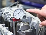
 For this build, we opted for OEM Honda bearings to have the highest degree of precision with respect to oil clearances. On the mains, we set the clearance at 0.0019″ for all of the main journals except the center. For the #3 center journal, we set the clearance a little looser at 0.0023″. The reason for adding additional clearance in the center main journal is to account for some of the runout in the crankshaft. On the rods, we set the clearance at 0.0023″. While at the top end (or just a couple ten-thousandths more than) of the factory specification, this clearance should be ideal for round-trips to 10,500 RPM or beyond when necessary.
Measure, Measure, Measure
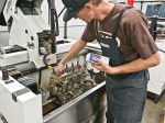
The more measures that can be made and recorded during the assembly of an engine, the better. Proper assembly of an engine will generally require assembly, measurement, disassembly, more measurement and a final assembly and recheck. While it takes additional time now, many issues can be found long before an engine is fired up. Speaking of fired up, we can’t wait to get the rest of this engine together next month. Stay tuned.
Engine Rebuilding Checklist
- Disassemble and clean engine and components.
- Magnaflux ferrous and Zyglo non-ferrous components that are to be reused.
- Take all pre-machining measurements:Piston-to-deck height: Main Journal Dimensions, Crankshaft Runout, Crankshaft main and rod journals.
- Balance crankshaft, rods and pistons.
- Check side clearance on rods and adjust if necessary.
- Sleeve block if necessary.
- Surface grind and/or lap engine block deck surface flat and to an Ra less than 30. This surface should be parallel to oil pan rails.
- Grind main caps and line bore block if necessary. Be sure to use same main studs/bolts that will be used in the engine torqued to spec.
- Use same main studs/bolts that will be used in the engine torqued to spec and line hone block keeping taper in each main journal to less than 0.0002″ and journal diameters within 0.0002″.
- Bore cylinders to within 0.005″ of final bore size.
- Install torque plate with the same head gasket, head studs, assembly lube and torque specification that is to be used. Use same torque wrench that will be used at final assembly.
- Rough, finish and plateau hone to final size and finish requirements.
- Check finish with profilometer during honing process. With dial bore gauge, check bores at top, middle and bottom of cylinder in both directions to ensure that cylinders are round and not tapered.
- Clean engine block.
- File-fit piston rings to each cylinder.
- Measure block’s main journals and rod’s big end journals.
- Use measurements of main journals, rod journals, crank main pins, crank rod pins and manufacturer’s bearing shell thickness to determine preliminary oil clearances.
- Order test bearing set.
- Using a dial-bore indicator, measure bore dimensions with bearings installed in rods and in block. There is a good chance that these dimensions will differ and that different bearings may need to be ordered depending on the desired final specification and variation allowed.
- Order additional rod and main bearings as required.
- Install finish bearings in block.
- Mock assemble crankshaft in engine with Plastigage.
- Measure Plastigage.
- Correct clearance issues with thinner or thicker bearings.
- Final install of crankshaft.
- Torque main caps to spec. Check that crank spins freely.
- Install oil squirters.
- Hang pistons on rods, install rings on pistons, ready piston-rod combination for installation.
- Using a tapered ring compressor to install each piston-rod combo making sure not to hit rod against cylinder wall or crankshaft journal.
- Using a rod-bolt stretch gauge and torque wrench. Torque cap bolts until the proper amount of stretch is achieved. Record all torque specs for each bolt.
- Rotate crank until #1 is at bottom dead center (BDC). The #1 and #4 rod caps will be accessible. Remove rod caps and double-check clearance with Plastigage. Final torque #1 and #4 rod caps if clearance if OK.
- Rotate crank until #1 is at top dead center (TDC). Rotate more if necessary so that the #2 and #3 rod caps will be accessible. Remove rod caps and double-check clearance with Plastigage. Final torque #2 and #3 rod caps if clearance is OK.
- Check the piston to deck clearance with short block assembled.


